


Page 11SKU 97503 For technical questions, please call 1-800-444-3353.
on the Torch Handle until the Welding
Wire feeds into the Torch Handle
about 2 inches. If necessary, move
the Torch Handle slightly in a circular
motion to help feed the Welding Wire
properly out of the Head Tube.
If the Welding Wire does not feed 14.
and the Spool is stationary, turn the
Welder off and unplug it. Tighten
the Tension Adjusting Knob on the
Wire Feed Assembly, and rewind the
Welding Wire slightly before retrying.
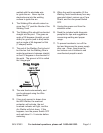
Feed the Welding Wire against scrap 15.
wood that is 2 to 3 inches away. If
the Wire stops instead of bending,
turn the Welder OFF and unplug it.
Tighten the Tension Adjusting Knob
more.
Turn the Welder OFF, unplug it, and 16.
discharge the electrode to ground.
Insert the contact tip onto the Welding
Wire and screw it rmly in place.
Replace the Nozzle and cut off any
excess Welding Wire over 1/2 inch.
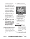
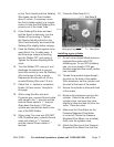
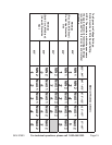
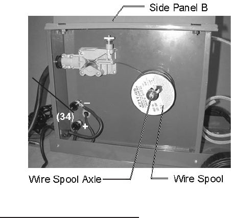
Check that +/– cables to connection 17.
Knobs (34) are correct. See photo
this page.
When using Non-ux wire and 18.
Protective gas, connect Ground cable
with clamp to the “-” terminal and the
Internal Power cable to “+” terminal.
Strap down the Argon / CO2 gas
cylinder and connect the hose to the
rear of the MIG Welder.
When using Flux-core wire (DO NOT 19.
USE Protective gas), connect Ground
cable with clamp to “+” terminal,
and the internal Power cable to “-”
terminal.
Close the Side Panel B (1).20.
Installing a gas cylinder
Do not use an Argon/Mixed pressure 21.
regulator/ow meter with CO2
shielding gas. To use CO2 shielding
gas, you must install a CO2 gas
pressure regulator/ow meter (neither
one included).
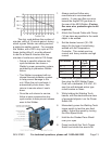
Thread the provided straps through 22.
the slots on the back of the welder.
With assistance, set the cylinder onto
the shelf at the back of the welder.
Secure the cylinder in place with both 23.
of the straps.
Remove the protective cap from the 24.
cylinder. Stand to the side of the
cylinder valve, and open the valve
slightly to blow dust and dirt from the
valve. Close the valve.
Make sure the Flow Adjust on the 25.
Pressure Regulator/Flow Meter
is turned off. Screw the Pressure
Regulator/Flow Meter (not included)
rmly onto the cylinder valve.
Attach the Gas Line to the Pressure 26.
Regulator/Flow Meter from the Gas
Connections