


Page 9SKU 97503 For technical questions, please call 1-800-444-3353.
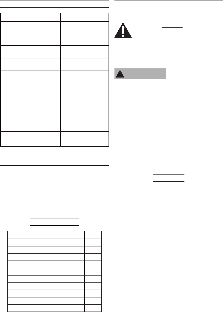
SPECIFICATIONS
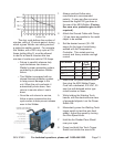
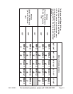
Welding Current 30 ~ 120 amps
Duty Cycle
20% at 105 amps;
40% at 75 amps;
90% at 50 amps;
100% at 30 amps
Input Power
230 VAC, 21 amps
(Peak) at 60 Hz
Open Circuit Voltage
(max)
36 VDC
Thermal Overload
Protection with Light
Automatic shutdown
and restart after cool
down
Wire Size
0.023 to 0.030 inch
steel and stainless
steel; 0.030 to 0.035
inch ux core and
aluminum
Welding Capacity
22 gauge to 3/16”
Steel
Wire Spool Size 2 lb. Spool
Weight 62.2 lbs.
UNPACKING
When unpacking, check to make sure
that the item is intact and undamaged. If
any parts are missing or broken, please
call Harbor Freight Tools at the number
shown on the cover of this manual as soon
as possible.
List of contents
Description Qty
Dual MIG Welder 1
Wheel 2
Axle 1
0.030” (0.8mm) Welding Tip 1
0.040 (1.0mm) Welding Tip 1
2 Pounds (0.030”) Flux Core Wire 1
Hand Held Shaded Face Shield 1
Brush Hammer 1
Welder Tip Close End Wrench 1
24” Strap For Gas Bottle 2
INITIAL SET UP
INSTRUCTIONS
Read the ENTIRE IMPORTANT
SAFETY INFORMATION section
at the beginning of this manual
including all text under
subheadings therein before set
up or use of this product.
TO PREVENT
SERIOUS INJURY
FROM ACCIDENTAL
OPERATION:
Turn the Power Switch of the
tool to its “OFF” position and
unplug the tool from its
electrical outlet before
assembling or making any
adjustments to the tool.
Note: For additional information regarding
the parts listed in the following pages,
refer to the Assembly Diagram near
the end of this manual.
Assembly
Slide the Axle (29) through the holes 1.
at the rear of the unit.
Secure both Wheels (28) to the Axle 2.
with the Locking Rings (42).
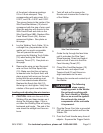
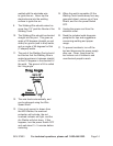
Lift up the Side Panel B (1) to 3.
expose the wire spool and Wire
Feed Mechanism (10). Pull back on
the Feed Tensioner (CC) to free the
Feed Tension Arm (DD) and lift it up.
Remove Wire Feed Wheel Cover
(AA) screws, pull out the cover, and
pull out the Wire Feed Wheel (BB).
See photo page 10.
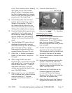
Note the two parallel grooves (one 4.
is wider) on the circumference of the
Wire Feed Wheel (BB). On the sides
WARNING