


SKU 98751 For technical questions, please call 1-800-444-3353. Page 7
FUNCTIONAL DESCRIPTION
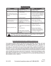
Specications
Air Pressure Range 70-120 PSI
Maximum Air
Pressure
120 PSI
Air Inlet 1/4” -18 NPT
Nail Type / Length
.113”-.131” Shank
Clipped or Full Head Nails
2” to 3-1/2” Length
Magazine
Capacity
21° - 60 Nails
28°/34° - 100 Nails
Air Consumption 3 CFM @ 90 PSI
Hose 3/8”
Safety Trigger Full Sequential Actuation
INITIAL ASSEMBLY
Read the ENTIRE IMPORTANT
SAFETY INFORMATION
section at the beginning of this
manual including all text under
subheadings therein before set
up or use of this product.
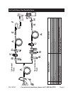
Note: For additional information regarding
the parts listed in the following pages,
refer to the Assembly Diagram near
the end of this manual.
Unpacking
When unpacking, check to make sure
that the item is intact and undamaged. If
any parts are missing or broken, please
call Harbor Freight Tools at the number
shown throughout the manual as soon as
possible.
• This air tool may be shipped with a
protective plug covering the air inlet.
Remove this plug before set up.
Air Supply
TO PREVENT
EXPLOSION:
Use only clean, dry, regulated,
compressed air to power this
tool. Do not use oxygen,
carbon dioxide, combustible
gases, or any other bottled
gas as a power source for this
tool.
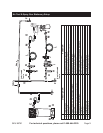
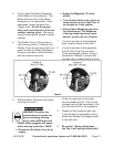
1. Connect a regulator valve, an in-line
shut off valve and 1/4” NPT air hose
(all sold separately) to the Quick Con-
nector. Use thread tape on all thread-
ed connections.The air hose must be
long enough to reach the work area
with enough extra length to allow free
movement while working. An in-line
shutoff ball valve is an important
safety device because it controls
the air supply even if the air hose
is ruptured. The shutoff valve
should be a ball valve because it
can be closed quickly.
See pages 8 and 9 for Air Tool
Setup procedures.
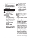
Note: If an automatic oiler system is not
used, add a few drops of Pneumatic
Tool Oil to the airline connection be-
fore operation. Add a few more drops
after each hour of continual use.
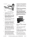
2. Attach an air hose to the compres-
sor’s air outlet. Connect the air hose
to the air inlet of the tool. Other com-
ponents, such as a connector and
quick coupler, will make operation
more efcient, but are not required.
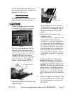
WARNING! TO PREVENT SERIOUS
INJURY FROM ACCIDENTAL
OPERATION:
Do not install a quick coupler on
the tool. Such a coupler contains
Functional Description
Initial Tool Set Up / Assembly
Rev 11a