


11
Leak Detection And Evacuation
Leak Testing
After all lines are connected, the entire system must be leak tested. The complete system should be pressurized to
not more than 150 PSIG with refrigerant and dry nitrogen. The use of an electronic type of leak detector is highly
recommended because of its greater sensitivity to small leaks. As a further check, it is recommended that this
pressure be held for a minimum of 12 hours and then rechecked. For a satisfactory installation, the system must be
leak tight.
Leak detection can be carried out in the conventional manner. If HCFC or CFC tracer gas is used, care must be taken
to completely remove all traces of the gas prior to introducing HFC’s. Electronic leak detectors are now available that
will sense HFC’s. This is considered preferable since it removes the possibility of chlorine remaining in the system
after leak testing with HCFC’s and/or HCFC’s. There is a view that even small quantities of chlorine may act as a
catalyst encouraging copper plating and/or corrosion and should therefore be avoided.
Within the last several years, manufacturers have developed uorescent dye leak detection systems for use with
refrigerants. These dyes mix with the lubricant and, when exposed to an ultraviolet light, uoresce to indicate the
location of leaks. Copeland has tested and approved the Rigid “System Safe” dye and found it to be compatible with
the compressor materials in systems.
Evacuation
CAUTION: Do not use the refrigeration compressor
to evacuate the system. Do not start the
compressor while it is in a vacuum.
Due to the smaller molecule size of HFC’s, they will tend to leak more readily than CFC. Consequently, it is of
the utmost importance that proper system evacuation and leak detection procedures be employed. Copeland
recommends a minimum evacuation to 500 microns. In addition, a vacuum decay test is strongly recommended to
assure there is not a large pressure dierential between the system and vacuum pump. Good evacuation processes
include frequent vacuum pump oil changes and large diameter, short hose connections to both high and low sides
of the system preferably using bronze braided hose.
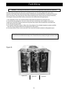
A good, deep vacuum pump should be connected to both the low and high side evacuation valves with copper tube
or high vacuum hoses (1/4” ID minimum). If the compressor has service valves, they should remain closed. A deep
vacuum gauge capable of registering pressure in microns should be attached to the system for pressure readings.
A shut-o valve between the gauge connection and vacuum pump should be provided to allow the system pressure
to be checked after evacuation. Do not turn o vacuum pump when connected to an evacuated system before
closing shut-o valve.
The vacuum pump should be operated until a pressure of 1,500 microns absolute pressure is reached – at which time
the vacuum should be broken with the refrigerant to be used in the system through a drier until the system pressure
rises above “0” psig.
NOTE: Refrigerant used during evacuation can not be vented.
Reclaim all used refrigerant. EPA regulations are constantly
being updated. Ensure your procedures follow correct regulations.
Repeat this operation a second time.
Open the compressor’s service valves and evacuate the entire system to 500 microns absolute pressure.
Raise the pressure to 2 psig with the refrigerant and remove the vacuum pump.