


308398 15
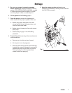
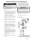
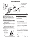
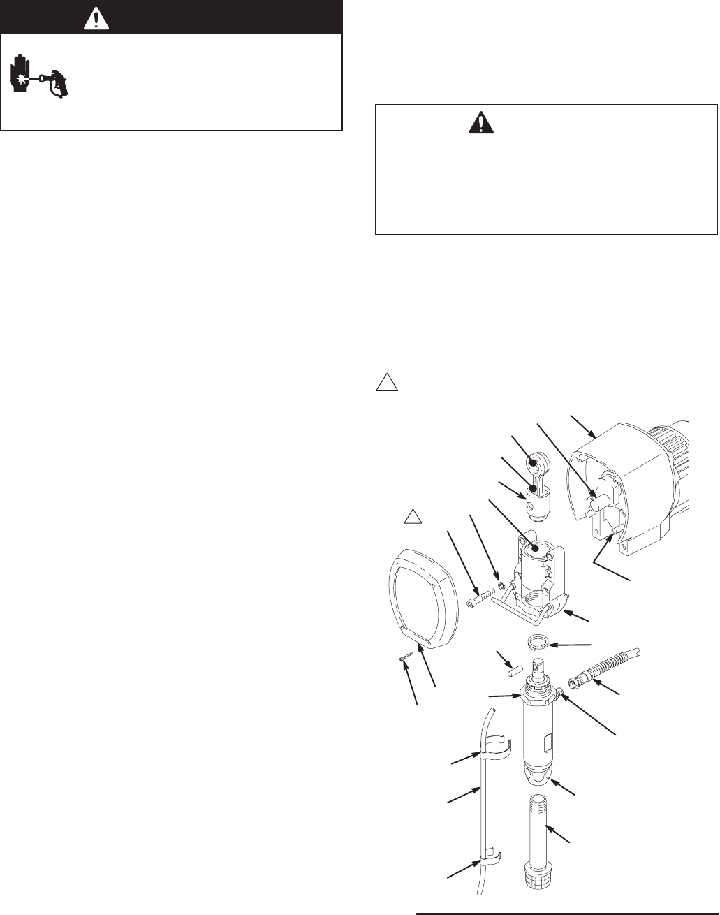
Bearing Housing & Connecting Rod
WARNING
INJECTION HAZARD
To reduce the risk of serious injury,
whenever you are instructed to relieve
pressure, follow the Pressure Relief
Procedure on page 10.
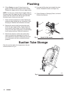
NOTE: Steps 1 to 13 refer to Fig. 7.
1. Relieve pressure.
2. Remove the screws (68) and the front cover (23).
3. Remove the spring clips (112, 114) and the drain
hose (113). Unscrew the suction tube (30) from the
pump, holding a wrench on the pump intake valve
(B) to keep the pump from loosening.
4. Disconnect the pump outlet hose (59) from the
displacement pump outlet nipple (87).
5. Use a screwdriver to push up the retaining spring
(26) at the top of the pump. Push the pin (25) out
the rear.
6. Loosen the jam nut (27) with an adjustable
wrench. Unscrew and remove the displacement
pump.
7. Use a hex key wrench to remove the four screws
(73) and lockwashers (74) from the bearing hous-
ing (21).
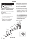
8. While pulling the connecting rod (22) with one
hand, lightly tap the lower rear of the bearing
housing (21) with a plastic mallet to loosen it from
the drive housing (20). Pull the bearing housing
and the connecting rod assembly (22) off the drive
housing.
9. Inspect the crank (A) for excessive wear and
replace parts as needed.
10. Evenly lubricate the inside of the bronze bearing
(C) in the bearing housing (21), and the inside of
the connecting rod link (D), with high–quality motor
oil (do not use grease). Liberally pack the roller
bearing (E) in the connecting rod assembly (22)
with bearing grease.
11. Assemble the connecting rod (22) and bearing
housing (21).
12. Clean the mating surfaces of the bearing and drive
housings.
13. Align the connecting rod with the crank (A) and
carefully align the locating pins (F) in the drive
housing (20) with the holes in the bearing housing
(21). Push the bearing housing onto the drive
housing or tap it into place with a plastic mallet.
CAUTION
DO NOT use the bearing housing screws (73) to
align or seat the bearing housing with the drive
housing. These parts must be aligned using the
locating pins (F), to help avoid premature bearing
wear.
14. Install the screws (73) and lockwashers (74) on the
bearing housing. Tighten evenly to 40 "5 ft-lbs
(54 "7 Nm).
15. Refer to Installing the Pump on page 31.
Fig. 7
27
22
114
113
112
03472
30
25
23
68
26
21
59
87
D
E
A
F
20
74
B
C
1 Torque the screw to
40 "5 ft-lbs (54 "7 Nm).
73
1
Model 231326 Shown