


30839824
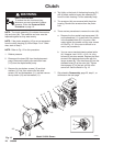
Reassembly
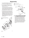
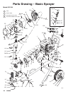
1. Install the clutch housing (2), capscrews (8) and
lockwashers (9) on the engine. See Fig. 18.
2. Install the engine shaft key (13). See Fig. 18.
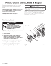
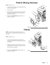
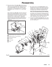
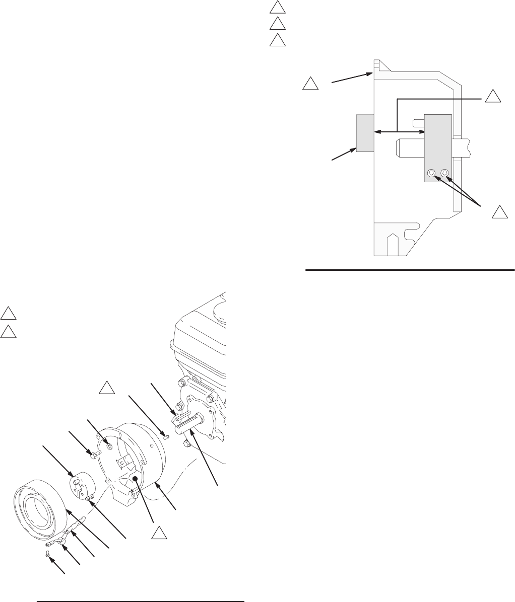
3. Press the clamp (3) onto the engine shaft (A).
Maintain the 1.99 "0.01 in. (50.55 "0.25 mm)
dimension shown in Fig. 19.
To check the dimension, place a rigid, straight
steel bar (B) across the face of the clutch housing
(2). Use an accurate measuring device to measure
the distance between the bar and the face of the
clamp. Adjust the clamp as necessary. Torque the
two screws (16) to 125 "10 in-lb (14 "1.1 Nm).
4. Connect the wires of the wire harness (96) to the
screws (98) in both places on the field (wires can
be attached to either connection). Pull the plastic
caps (C) up and snap them over the screws. Install
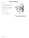
the field (6) in the clutch housing (2). Work the
wire harness through the slot in the clutch housing,
With the setscrew holes in the field and the clutch
housing (2) aligned, tighten the setscrews (12)
oppositely and evenly, to 27 " 3 in-lb (3.1 "0.3
Nm). See Fig. 18.
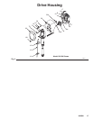
Fig. 18
6
3
8
9
2
13
98
96
16
A
03482
C
12
1
2
Torque the screws oppositely and
evenly to 27 "3 in-lb (3.1 "0.3 Nm).
Slot.
2
1
Fig. 19
16
2
B
03483
1
3
2
The face of the housing.
1.99 "0.01 in. (50.55 "0.25 mm).
Torque the screws to 125 "10 in-lb (14 "1.1 Nm)
1
2
3
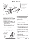
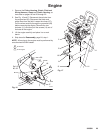
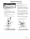
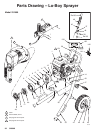
5. Place the engine (1) assembly on the cart. Align
the mounting holes. Carefully guide the engine
wire (D) and wiring harness (96) from the field,
through the appropriate grommets (66) in the
mounting plate (E). Install the flange screws (14)
and locknuts (111). Torque to 15 ft-lb (20.4 Nm).
Install the capscrew (15), lockwasher (80) and
washer (99) from under the engine mounting plate
to the clutch housing (2). Connect the engine wire
(D) to the red wire, and connect the black and
white wires as shown in the Detail drawing in
Fig. 20.