


308398 25
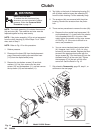
Reassembly
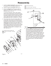
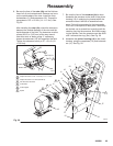
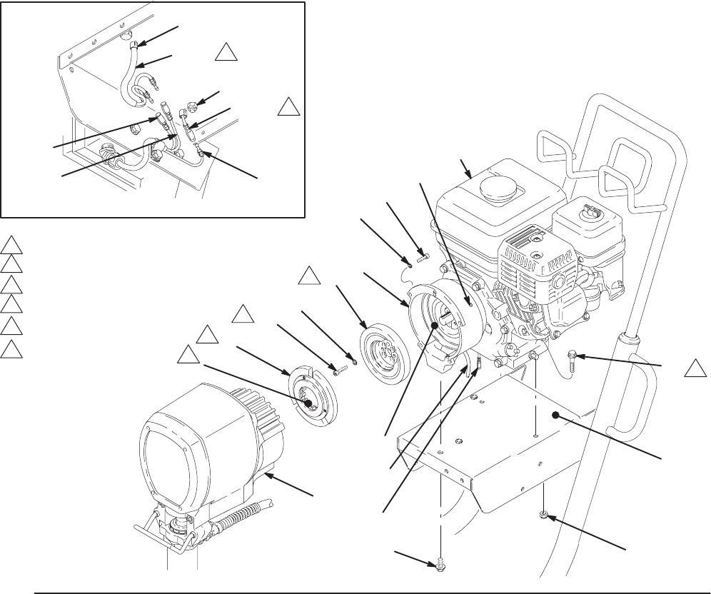
6. Be sure the face of the rotor (4b) and the field are
free of all oil and contaminants. Remove any burrs
on the outside edge of the rotor. Install the rotor,
lockwashers (11) and capscrews (16). Torque the
capscrews to 125 "10 in-lb (14 "1.1 Nm). See
Fig. 20.
After installing the rotor (4b), check the clearance
between the outside diameter of the rotor and the
inside diameter of the field. The clearance must be
at least 0.010 in. (0.25 mm) all the way around.
Use shim stock or feeler gauge. If necessary,
loosen the setscrews (12) and reposition the field.
Tighten the setscrews evenly to 27 "3 in-lb (3.1
"0.3 Nm).
7. Be sure the face of the armature (4a) is clean.
Assemble the armature to the shaft in the pinion
housing (19). A retaining ring located within the
armature makes it difficult to assemble these
parts. Follow this procedure for the best results.
First, lock a few splines of both parts. While they
are locked, use a screwdriver to gently push the
retaining ring into the armature, and finish engag-
ing the splines. Push the armature onto the shaft
until it contacts the ring (19m). See Fig. 20.
8. Assemble the pinion housing (19) to the clutch
housing, using the capscrews (10) and lockwash-
ers (11). See Fig. 20.
Fig. 20
E
66
Ref 14,111
RED
BLACK
WHITE
111
15
4a
11
4b
6
2
1
16
96
D
19
12
14
11
10
1
3
4
2
Torque the screw to 125 "10 in-lb (14 "1.1 Nm).
Torque the screw to 15 ft–lb (20.4 N.m).
The face must be clean.
1
2
3
To the field.
5 To the engine.
6 Spline
6
4
Ref 96
Ref D
5
3
03478A
03484B