


30839820
Clutch
WARNING
INJECTION HAZARD
To reduce the risk of serious injury,
whenever you are instructed to relieve
pressure, follow the Pressure Relief
Procedure on page 10.
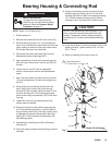
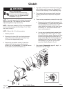
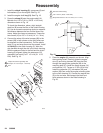
NOTE: The clutch assembly (4) includes the armature
(4a) and rotor (4b). The armature and rotor must be
replaced together so they wear evenly.
NOTE: If the pinion assembly (19) is not yet separated
from the clutch housing (2), follow Steps 1 to 4. Other-
wise, start at Step 5.
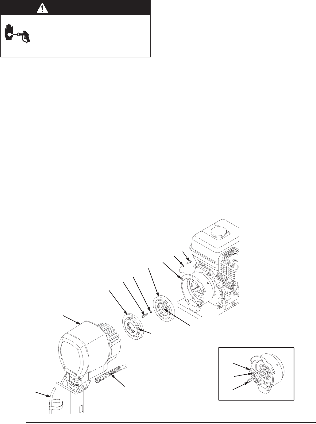
NOTE: Refer to Fig. 12 for this procedure.
1. Relieve pressure.
2. Disconnect the hose (59) from the displacement
pump. Remove the spring clips and drain hose
(113) from the displacement pump.
3. Remove the two bottom screws (10) and lock-
washers (11) first, then remove the two side
screws (10) and lockwashers (11), and last remove
the top screw (10) and lockwasher (11).
4. Tap lightly on the back of the bearing housing (21)
with a plastic mallet to loosen the assembly (D)
from the clutch housing. Pull the assembly away.
5. The armature (4a) was removed with the pinion
housing. Remove the armature from the pinion
hub.
6. There are two procedures to remove the rotor (4b).
a. Remove the four socket head capscrews (16)
and lockwashers (11). Install two of the screws
in the threaded holes (E) in the rotor. Alter-
nately tighten the screws until the rotor comes
off. See Fig. 12. If the rotor is difficult to re-
move, use procedure b.
b. You can use a standard steering wheel puller
(A). However, two 1/4–22– x 3 or 4 in. long
screws (B) are also needed. Replace the short
screws of the steering wheel puller with the
longer screws (B). Turn the screws (B) into the
threaded holes (E) of the rotor (4b). Tighten
the capscrew (C) of the tool until the rotor
comes off. See the Detail in Fig. 12.
7. Skip ahead to Reassembly, page 25, step 6., or
continue on the next page.
05798A
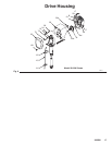
Fig. 12
D
A
B
C
E
19
10
11
59
113
2
16
4a
4b
11
Model 231326 Shown