


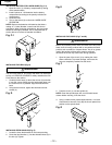

6. If the quill moves up and down as easily as you desire,
tighten the inner nut (4) with the adjustable wrench. If too
loose, repeat steps 2 through 4 to tighten. If too tight,
reverse steps 3 and 4. DO NOT OVERTIGHTEN and
restrict quill movement.
7. Replace the jam nut (3) and tighten against the inner nut
(4) to prevent the inner nut from reversing.
To avoid injury from an accidental start, ALWAYS make sure
the switch is in the OFF position, the switch key is removed,
and the plug is not connected to the power source outlet
before making belt adjustments.
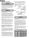
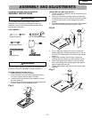
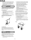
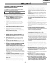
BELT TENSION (Fig. K)
1 To release the belt tension, turn the belt tension lock
knob (1) on the right side of the drill press head
counterclockwise.
2. To tighten the belts, push the motor mounting plate (2)
toward the rear (motor) end.
3. To loosen the belts, pull the motor mounting plate (2)
toward the front (switch) end.
4. Lock the belt tension lock knob (1) by turning clockwise.
NOTE: Belt tension is correct if the belt deflects
approximately 1/2 inch when pressed at its center.
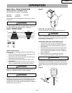
THE LASER GUIDE
Your tool is equipped with our latest innovation, the Laser
Guide, a battery powered device using Class IIIa laser
beams. The laser beams will enable you to preview the drill
bit path on the workpiece to be drilled before you begin your
operation.
AVOID DIRECT EYE CONTACT
A Laser light is radiated when the laser guide is turned on.
Avoid direct eye contact. Always turn off the laser and unplug
the drill press from the power source before making any
adjustments.
• A laser pointer is not a toy and should not come into
hands of children. Misuse of this appliance can lead to
irreparable eye injuries.
• Any adjustments to increase the laser power is forbidden.
• When using the laser pointer, do not point the laser beam
towards people and / or reflecting surfaces. Even a laser
beam of lower intensity may cause eye damage.
Therefore, do not look directly into the laser beam.
• If the laser pointer is stored for more than three months
without use, please remove the batteries to avoid
damage from possibly leaking batteries.
• The laser pointer includes no user serviceable
components. Never open the housing for repair or
adjustments.
• On units equipped with the Laser-Guide attachment,
repairs shall only be carried out by the laser
manufacturer or authorized agent.
• Laser Warning label: Max output <5mW DIODE LASER:
630-660nm, Complies with 21CFR 1040.10 and 1040. 11.
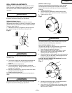
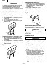
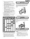
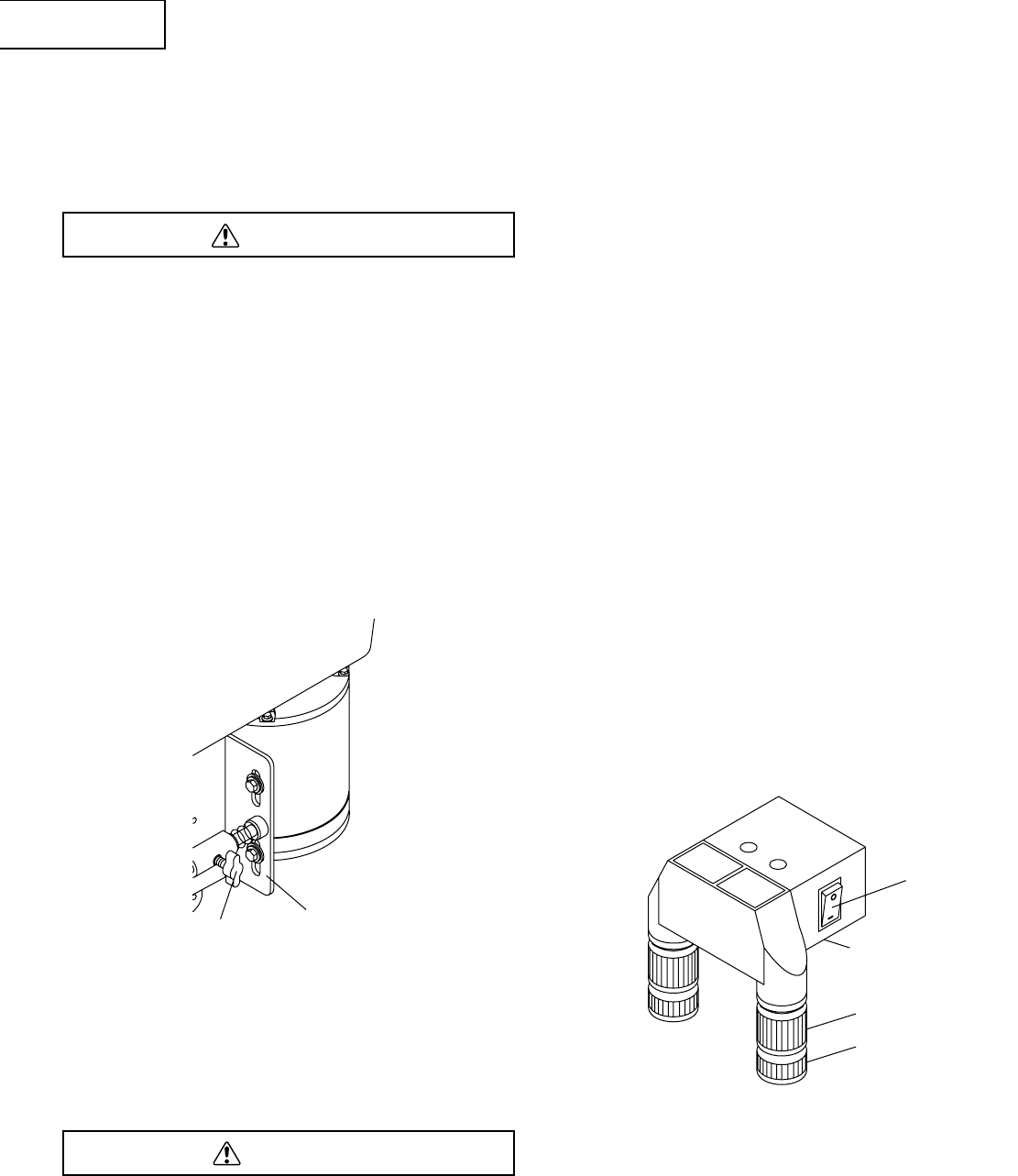
ADUSTING THE LASER LINES (Fig. L)
How to check and adjust the Laser Beam Alignment:
Check the laser beam alignment to ensure the intersection of
the laser lines precisely at the spot where the drill bit meets
the workpiece. If it is not, the laser lines should be adjusted
using the laser adjustment knobs located on the opposite
sides of the head assembly.
1. Mark an “X” on a piece of scrap wood.
2. Insert a small drill bit into the chuck and align its tip to
the intersection of the lines of the “X”.
3. Secure the board to the table.
4. Turn on the laser (3) and verify the laser lines align with
the “X” on the workpiece.
5. If the laser lines do not align, loosen knobs (2) on each
side of the laser module and rotate the lasers (4) until the
lines meet in the center of the “X”. Retighten the knobs to
secure.
DANGER
WARNING
Fig. K
1
Fig. L
3
4
2
1
2
– 14 –
English