


10
English
The laser line is adjusted to the width of the saw blade at the time of
factory shipment. Adjust the positions of the saw blade and the laser
line taking the following steps to suit the use of your choice.
Fig. 14
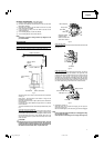
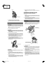
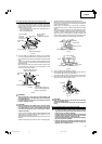
(1) Light up the laser marker and make a groove of about 3/16 in. (5mm)
deep on the workpiece that is about 1-1/2 in. (38mm) in height and
3-1/2 in. (89mm) in width. Hold the grooved workpiece by vise as it
is and do not move it.
Fig. 15
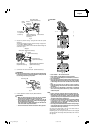
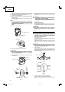
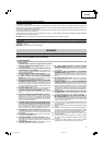
(2) Then insert a 4mm hex. bar wrench in the 12 diameter hole on the
side of the gear case, turn the hex. socket set screw to move the
laser line. (If you turn the Hex. socket screw clockwise, the laser line
will shift to the right and if you turn it counterclockwise, the laser
line will shift to the left.) When you work with the ink line aligned
with the left side of the saw blade, align the laser line with the left
end of the groove. (Fig. 16) When you align it with the right side of
the saw blade, align the laser line with the right side of the groove.
Fig. 16
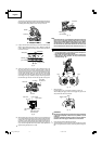
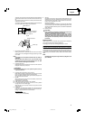
(3) After adjusting the position of the laser line, draw a right-angle ink
line on the workpiece and align the ink line with the laser line. When
aligning the ink line, slide the workpiece little by little and secure it
by vise at a position where the laser line overlaps with the ink line.
Work on the grooving again and check the position of the laser line.
If you wish to change the laser line’s position, make adjustments
again following the steps from (1) to (3).
Saw blade
Marking
(pre-marked)
Workpiece
Cutting width
Fig. 17
NOTE:
Check and make sure on a periodic basis if the position of the laser
line is in order. As regards the checking method, draw a right-angle
ink line on the workpiece with the height of about 1-1/2 in. (38mm)
and the width of 3-1/2 in. (89mm), and check that the laser line is in
line with the ink line [The deviation between the ink line and the
laser line should be less than the ink line width (0.5mm)]. (Fig. 17)
PRACTICAL APPLICATIONS
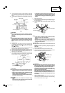
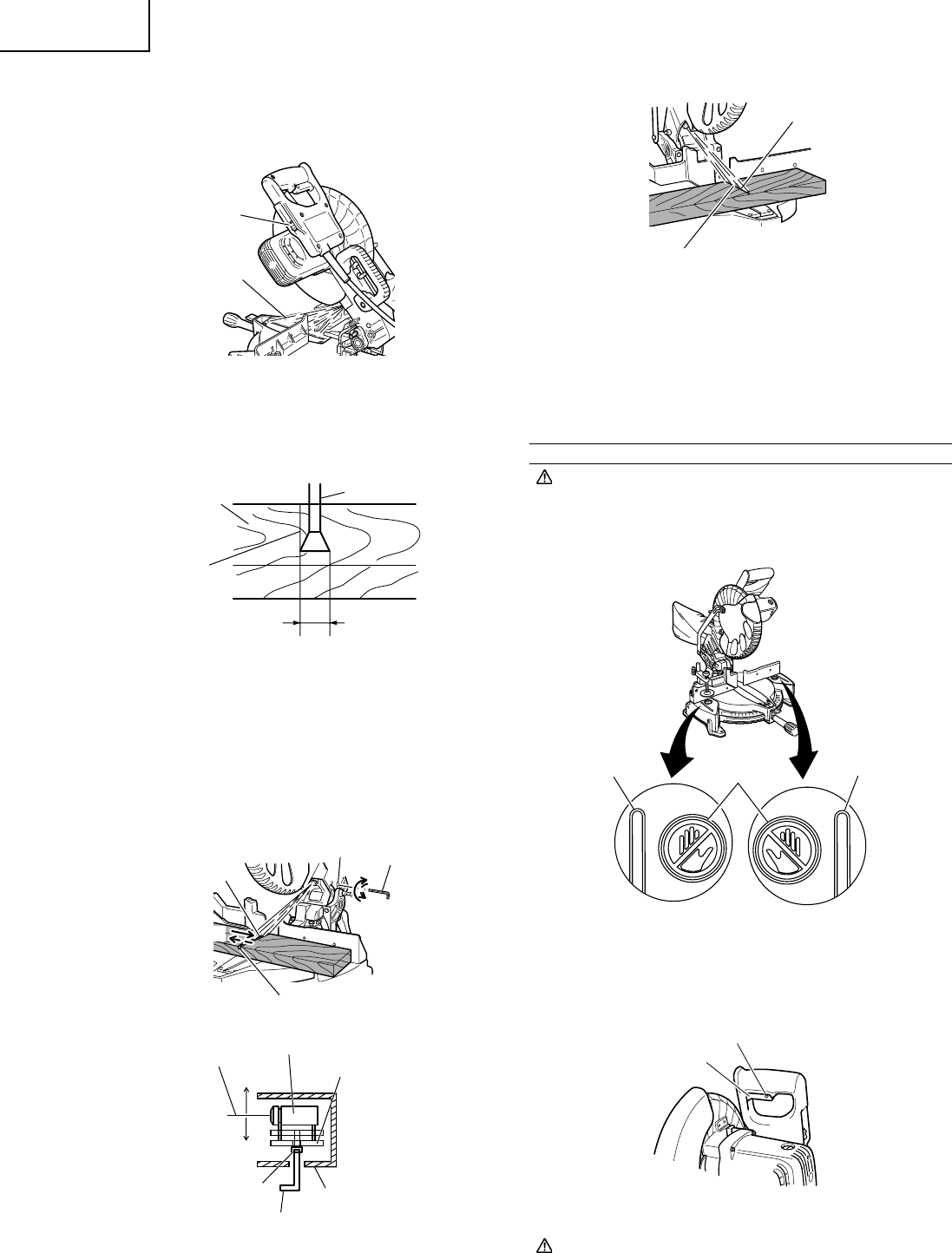
WARNING:
* To avoid personal injury, never remove or place a workpiece on
the table while the tool is being operated.
* Never place your limbs inside of the line next to warning sign
while the tool is being operated. This may cause hazardous
conditions (see Fig. 18).
Fig. 18
1. Switch operation
Pull the trigger to turn on the switch, release it to shut it off.
After releasing the trigger, make sure the trigger has gone all the
way back and the switch is turned off.
Fig. 19
WARNING:
This will ensure that the power tool cannot be turned on accidentally
or by someone (especially a child) who is not qualified to use the
power tool.
To prevent unauthorized operation of this tool, insert a padlock to
the hole in the switch trigger to disable the use of the switch.
2. Using the Vise Assembly (Standard accessory)
(1) The vise assembly can be mounted on either the left fence {Fence
(B)} or the right fence {Fence (A)} by loosening the 6mm wing bolt
(A).
Switch
Laser line
Laser marker
Laser line
Left
Right
Hex socket
bolt
Hex bar wrench
(Accessories)
Laser holder
Gear case
Laser line
Marking
(pre-marked)
Line
Warning
sign
Line
Trigger switch
Hole
Turn
Groove
Laser line
4mm Hex.
bar wrench
Move
ø12 Hole
01Eng_C10FCH2_US 6/15/07, 19:0910