


14
English
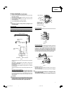
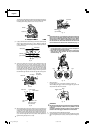
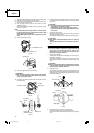
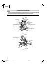
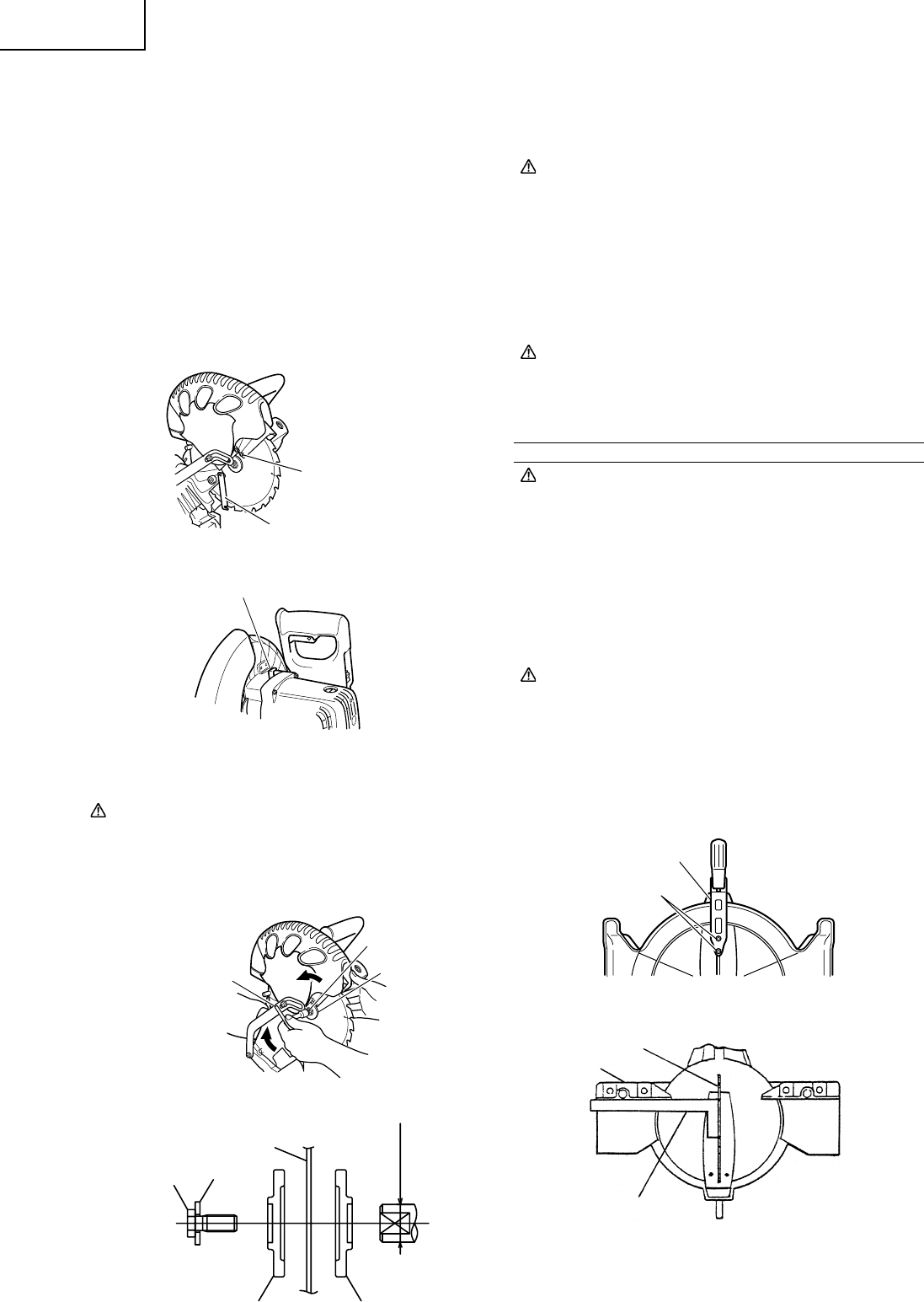
1. Mounting the saw blade (Fig. 33-a, Fig. 33-b, Fig. 33-c and Fig. 33-d)
(1) Rotate the lower guard (plastic) to the top position.
(2) Use the driver to loosen the 4mm screw fastening the spindle cover
and then remove the spindle cover.
(3) Press in spindle lock and loosen bolt with 10mm box wrench
(standard accessory).
Since the bolt is left-hand threaded, loosen by turning it to the right
as shown in Fig. 33-c.
NOTE:
If the spindle lock cannot be easily pressed in to lock the spindle,
turn the bolt with 10mm box wrench (standard accessory) while
applying pressure on the spindle lock.
The saw blade spindle is locked when the spindle lock is pressed
inward.
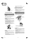
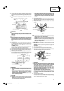
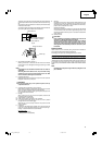
(4) Remove the bolt and washer (D)
Fig. 33-a
Fig. 33-b
(5) Lift the lower guard and mount the saw blade.
WARNING:
When mounting the saw blade, confirm that the rotation indicator
mark on the saw blade and the rotation direction of the gear case
(see Fig. 1) are properly matched.
(6) Thoroughly clean washer (D) and the bolt, and install them onto the
saw blade spindle.
Fig. 33-c
Fig. 33-d
(7) Press in the spindle lock and tighten the bolt by turning it to the left
by standard accessorie’s wrench (10mm box wrench) as indicated
in Fig. 33-c.
CAUTION:
* Confirm that the spindle lock has returned to the retract position
after installing or removing the saw blade.
* Tighten the bolt so it does not come loose during operation.
Confirm the bolt has been properly tightened before the power
tool is started.
2. Dismounting the saw blade
Dismount the saw blade by reversing the mounting procedures
described in paragraph 1 above.
The saw blade can easily be removed after lifting the safety cover.
CAUTION:
Never attempt to install saw blades larger than 10 in. (255mm) in
diameter.
Always install saw blades that are 10 in. (255mm) in diameter or
less.
MAINTENANCE AND INSPECTION
WARNING:
To avoid an accident or personal injury, always confirm that the
trigger switch is turned OFF and the power plug has been
disconnected from the receptacle before performing any
maintenance or inspection of this tool.
1. Inspecting the saw blade
Always replace the saw blade immediately upon the first sign of
deterioration or damage.
A damaged saw blade can cause personal injury and a worn saw
blade can cause ineffective operation and possible overload to the
motor.
CAUTION:
Never use a dull saw blade. When a saw blade is dull, its resistance
to the hand pressure applied by the tool handle tends to increase,
making it unsafe to operate the power tool.
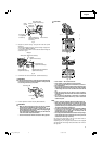
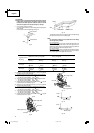
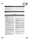
2. Inspecting the lever
If the M6 hexagonal head bolts (2) are loose, align the sides of the
fence and saw blade with the steel square. After adjusting the saw
blade and fence to a ninety-degree angle, tighten the lever securing
hexagonal head bolts (2).
Fig. 34-a
Fig. 34-b
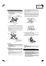
3. Inspecting the carbon brushes (Fig. 35 and Fig. 36)
The carbon brushes in the motor are expendable parts.
If the carbon brushes become excessively worn, motor trouble might
occur.
5/8 in. (15.9mm)
Bolt
Washer
Saw blade
Washer (D)
(Chamfering side)
Washer (D)
Fence
Saw blade
Steel square
Spindle cover
4 mm Machine screw
Spindle lock
10mm Box wrench
Washer (D)
6 mm Bolt
Hex. head bolt
Lever
01Eng_C10FCH2_US 6/15/07, 19:1014