


7
English
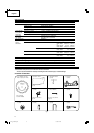
OPTIONAL ACCESSORIES...sold separately
1
Extension Holder and Stopper (Code No. 322710)
2
Saw blade 10 in. (255mm) TCT Saw blade for wood cut (Total teeth:
60) (Code No. 976472)
3
Saw blade 10 in. (255mm) TCT Saw blade for aluminum cut (Total
teeth: 100) (Code No. 319658)
4
Crown molding Vise Ass’y (Code No. 322712) (Include Crown
molding Stopper (L))
5
Crown molding Stopper (L) (Code No. 322713)
6
Crown molding Stopper (R) (Code No. 322714)
NOTE:
Accessories are subject to change without any obligation on the
part of the HITACHI.
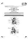
APPLICATIONS
Wood and aluminum sash.
PREPARATION BEFORE OPERATION
Make the following preparations before operating the power tool:
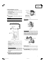
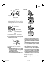
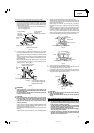
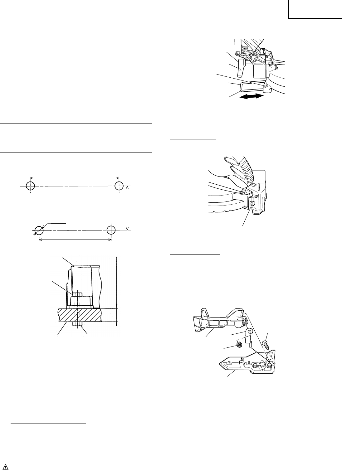
1. Installation
Fig. 4
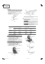
Attach the power tool to a level, horizontal work bench in accordance
with Fig. 4.
Select 5/16 in. (8mm) diameter bolts suitable in length for the
thickness of the work bench.
Bolt length should be at least 1-3/8 in. (35mm) plus the thickness of
the work bench.
For example, use 2-11/32 in. (60mm) or larger bolts for a 1 in. (25mm)
thick work bench.
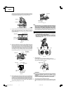
The holder attached to the rear of the base helps stabilize the power
tool.
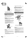
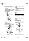
Holder (B), clamp lever adjustment:
Attach the included holder (B) in the position as shown in figure 5
and adjust the holder (B) until its bottom surface contacts the work
bench surface. After adjustments, securely tighten the 6mm bolt with
the included 10mm box wrench. Loosen the M6 × 20 screw on the
clamp lever and attach to a position where the clamp lever can be
easily operated.
CAUTION:
Attach the power tool to a work bench with bolts (6mm), and if the
turntable has been swiveled 45° degrees or more, be careful not to
let the hand that is holding the side handle get caught between the
side handle and heads of bolts (6mm). Injuries could result.
Fig. 5-a
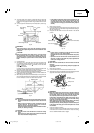
Install the side handle
Remove the M10 bolt and install the side handle that came enclosed
with this unit.
Fig. 5-b
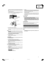
Install the sub fence (B)
In the case of direct angle cutting and angle cutting, use the sub
fence. The sub fence (B) can be installed on the right side of the
guide fence (B). Place the attached plate (A) in the position as shown
in figure 5-c, insert the tip in the groove of fence (B) and
simultaneously, insert flathead screw M6 into fence (B), sub fence
(B), and plate (A), then tighten nylon nut M6 with the included 10mm
box wrench until the sub fence (B) can smoothly rotate. Then, you
can realize stable cutting of the material with a wide back face.
Fig. 5-c
2. Releasing the locking pin
When the power tool is prepared for shipping, its main parts are
secured by a locking pin.
Move the handle slightly so that the locking pin can be disengaged.
NOTE:
Lowering the handle slightly will enable you to disengage the locking
pin more easily and safely.
The lock position of the locking pin is for carrying and storage only.
1 in. (25mm) Thick bench
5/16 in. (8mm)
Bolt
Base
Work bench
5/16 in. (8mm) Nut
Sub fence (B)
M6 Flat screw
Fence (B)
Plate (A)
M6 Nylon nut
Move
Adjust the holder
until its bottom
surface contacts the
work bench surface.
Holder (B)
M6 × 20 Screw
Clamp lever
6mm Bolt
M10 Bolt
11/32 in. (9mm)
4 Holes
8-1/4 in.
(210mm)
14-1/6 in. (360mm)
16-3/8 in. (416mm)
01Eng_C10FCH2_US 6/15/07, 19:097