


8
English
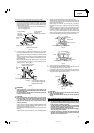
Fig. 6
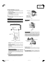
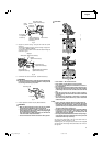
3. Installing the dust bag, holder, stopper and vises
(The holder and stopper are optional accessories.)
Attach the dust bag and vise assembly as indicated in Fig. 1 and Fig.
2.
BEFORE USING
1. Make sure the power source is appropriate for the tool.
WARNING:
Never connect the power tool unless the available AC power source
is of the same voltage as that specified on the nameplate of the
tool.
Never connect this power tool to a DC power source.
2. Make sure the trigger switch is turned OFF.
WARNING:
If the power cord is connected to the power source with the trigger
switch turned ON the power tool will start suddenly and can cause
a serious accident.
3. Check the saw blade for visible defects.
Confirm that the saw blade is free of cracks or other visible damage.
4. Confirm that the saw blade is attached securely to the power tool.
Using the supplied 10mm box wrench, tighten the bolt on the saw
blade spindle to secure the saw blade.
For details, see Fig. 33-a, Fig. 33-b, Fig. 33-c and Fig. 33-d in the
section on “SAW BLADE MOUNTING AND DISMOUNTING”.
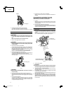
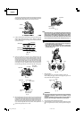
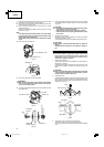
5. Check the lower guard for proper operation.
Lower guard is designed to protect the operator from coming into
contact with the saw blade during operation of the tool.
Always check that the lower guard moves smoothly and covers the
saw blade properly.
Fig. 7
WARNING:
NEVER OPERATE THE POWER TOOL if the safety cover does not
function smoothly.
6. Confirm the position of the spindle lock before using the tool.
After installing the saw blade, confirm that the spindle lock has been
returned to the retract position before using the power tool (see Fig.
33-b).
7. Check the Power Receptacle.
To prevent overheating, accidental stopping or intermittent
operation, confirm that the power cord plug fits properly in the
electrical receptacle and does not fall out after it is inserted. Repair
or replace the receptacle if it is faulty.
8. Confirm the tool’s power cord is not damaged.
Repair or replace the power cord if an inspection indicates that it is
damaged.
AFTER CONNECTING THE POWER PLUG TO AN
APPROPRIATE AC POWER SOURCE, CHECK THE
OPERATION OF THE TOOL AS FOLLOWS:
9. Trial Run
After confirming that no one is standing behind, the power tool start
and confirm that no operating abnormalities exist before attempting
a cutting operation.
10. Inspect the rotating stability of the saw blade.
For precise cutting, rotate the saw blade and check for deflection to
confirm that the blade is not noticeably unstable; otherwise vibrations
might occur and cause an accident.
BEFORE CUTTING
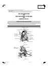
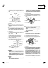
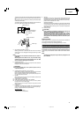
1. Oblique angle
Before the power tool is shipped from the factory, it is adjusted for
0°, left 45° bevel cutting angle with the 8mm bolt (A) and the 8mm
bolt (B).
When changing the adjustment, change the height of the 8mm bolt
(A) or the 8mm bolt (B) by turning them. (Fig. 8-a, Fig. 8-b)
Fig. 8-a
Fig. 8-b
2. Securing the workpiece
WARNING:
Always clamp or vise to secure the workpiece to the fence; otherwise
the workpiece might be thrust from the table and cause bodily harm.
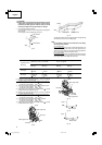
3. Installing the holders ... (Optional accessory)
The holders help keep longer workpieces stable and in place during
the cutting operation.
(1) As indicated in Fig. 9, use a steel square for aligning the upper edge
of the holders with the base surface.
Loosen the 6mm wing nut. Turn a height adjustment bolt 6mm, and
adjust the height of the holder.
(2) After adjustment, firmly tighten the wing nut and fasten the holder
with the 6mm wing bolt (optional accessory). If the length of Height
Adjustment Bolt 6mm is insufficient, spread a thin plate beneath.
Make sure the end of Height Adjustment Bolt 6mm does not protrude
from the holder.
8mm Bolt (B) (Stopper
for left 45° bevel angle)
Handle
Locking pin
Lower guard
8mm Bolt (A)
(Stopper for 0°)
Indicator (B)
(For bevel scale)
01Eng_C10FCH2_US 6/15/07, 19:098