


12
English
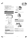
CAUTION:
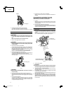
Always secure the workpiece with the right hand side for compound
cutting. Never rotate the table to the right for compound cutting,
because the saw blade might then contact the clamp or vise that
secures the workpiece, and cause personal injury or damage.
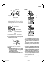
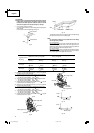
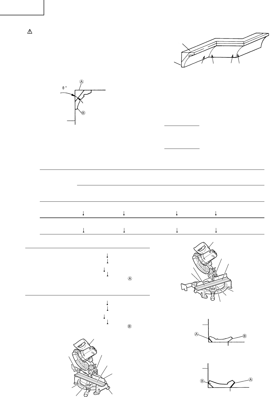
7. Crown molding cutting procedures
Fig. 24 shows two common crown molding types having angles of
(θ) 38° and 45°.
For the typical crown molding fittings, see Fig. 25.
Fig. 24
Fig. 25
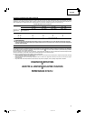
The table below shows the miter angle and the bevel angle settings
that are ideal for the two crown molding types.
NOTE:
For convenience, positive stops are provided for the miter setting
(left and right 31.6°) positions.
For miter cut setting
If the turntable has been set to either of the angles described, move
the turntable adjusting side handle a little to the right and left to
stabilize the position and to properly align the miter angle scale and
the tip of the indicator before the operation starts.
For bevel cut setting
Move handle on bevel section to the left and check that the position
is stable and that the bevel angle scale and the tip of the indicator
are properly aligned. Then tighten the clamp lever.
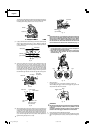
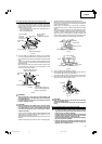
(1) Setting to cut crown moldings at positions
1
and
4
in Fig. 25 (see
Fig. 26; tilt the motor head to the left):
1
Turn the turntable to the right and set the Miter Angle as follows:
* For 45° type crown moldings: 35.3° ( mark)
* For 38° type crown moldings: 31.6° ( mark)
2
Tilt the motor head to the left and set the Bevel Angle as follows:
* For 45° type crown moldings: 30° ( mark)
* For 38° type crown moldings: 33.9° ( mark)
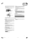
3
Position the crown molding so that the upper surface ( in Fig. 24)
contacts the fence as indicated in Fig. 28.
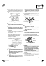
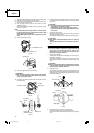
(2) Setting to cut crown moldings at positions
2
and
3
in Fig. 25 (see
Fig. 27; tilt the head to the left):
1
Turn the turntable to the left and set the Miter Angle as follows:
* For 45° type crown moldings: 35.3° ( mark)
* For 38° type crown moldings: 31.6° ( mark)
2
Tilt the head to the left and set the Bevel Angle as follows:
* For 45° type crown moldings: 30° ( mark)
* For 38° type crown moldings: 33.9° ( mark)
3
Position the crown molding so that the lower surface ( in Fig. 24)
contacts the fence as in Fig. 29.
Fig. 26
To process crown molding at
positions 1 and 4 in Fig. 36.
To process crown molding at positions 2
and 3 in Fig. 36.
Type of Crown
Molding
45° Type
38° Type
Miter Angle
Setting
right 35.3°
(
mark)
right 31.6°
(
mark)
Miter Angle
Setting
left 35.3°
(
mark)
left 31.6°
(
mark)
Bevel Angle
Setting
left 30°
(
mark)
left 33.9°
(
mark)
Bevel Angle
Setting
left 30°
(
mark)
left 33.9°
(
mark)
Fig. 27
Fig. 28
Fig. 29
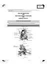
Table on base
Fence
Bevel angle scale
Fence (A)
Base
Miter angle scale
Turntable
Head
1
4
Bevel angle scale
Base
Miter angle scale
Turntable
Fence (B)
Head
3
2
Fence
Table on base
Wall
upper surface
Ceiling
lower surface
Ceiling
Wall
34
Inside corner Outside corner
1
2
01Eng_C10FCH2_US 6/15/07, 19:0912