


– 13 –
English
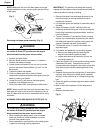
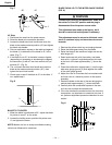
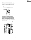
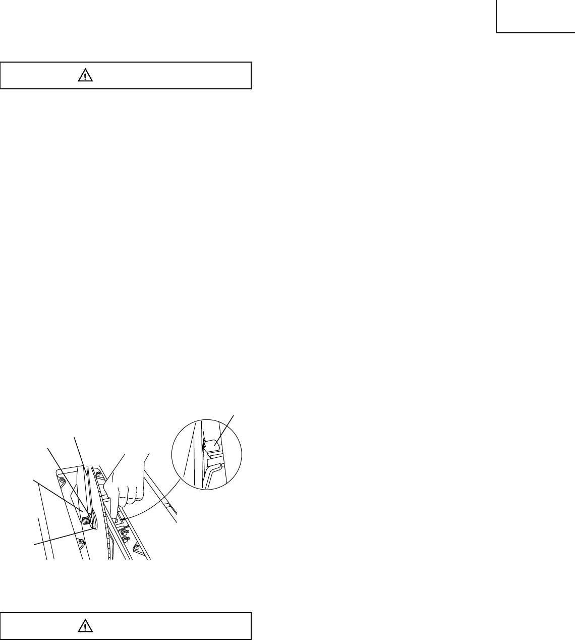
REMOVING THE BLADE (FIG. E)
To avoid injury from an accidental start, make sure
the switch is in the OFF position and the plug is
disconnected from the power source outlet.
1. Remove the table insert and raise the blade to the
maximum height by turning the blade elevation
handwheel clockwise.
2. Lift the blade guard and position it toward the rear of
the table.
3. Adjust the blade to the 90° vertical position by
unlocking the blade tilting lock knob and turning the
bevel tilting handwheel counterclockwise, and then
lock into position.
4. Pull the motor locking lever (1) toward the front of the
machine while spinning the blade until the latch locks
into place and the blade will no longer turn.
5. Place the blade wrench (3) on the arbor nut (4).
6. Loosen and remove the arbor nut and the flange by
pulling the wrench toward the front of the
machine.
7. Then remove the blade (6). Clean but do not remove
the inner blade flange (5) before reassembling the
blade.
Fig. E
INSTALLING A BLADE (FIG. E)
To avoid injury from an accidental start, make sure
the switch is in the OFF position and the plug is
disconnected from the power source outlet.
1. Place the blade onto the arbor with the blade teeth
pointing forward to the front of the saw.
2. Make sure the blade fits flush against the inner
flange.
3. Clean the outer blade flange and install it onto the
arbor and against the blade.
4. Thread the arbor nut onto the arbor, making sure the
flat side of the nut is against the blade, then hand-
tighten.
5. Pull the motor locking lever (1) toward the front of the
machine while spinning the blade until the latch locks
into place and the blade will no longer turn.
6. Place the wrench on the arbor nut and turn clockwise
(toward the rear of the saw table).
7. Replace the table insert and blade guard assembly.
Verify that the blade and blade guard splitter are
aligned. If they are not, refer to page 12, Aligning The
Blade Guard Splitter.
IMPORTANT: Do not operate this saw until the blade
and blade guard splitter are aligned and in working
order.
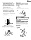
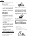
ADJUSTING THE 90° AND 45° POSITIVE STOPS
(FIG. F, G)
Your saw has positive stops that will quickly position
the saw blade at 90° and 45° to the table. Make
adjustments only if necessary.
90° Stop
1. Disconnect the saw from the power source.
2. Raise the blade to the maximum elevation.
3. Loosen the blade bevel lock handle and move the
blade to the maximum vertical position and tighten
the bevel lock handle.
4. Place a combination square on the table and against
the blade (1) to determine if the blade is 90° to the
table. (Fig. F)
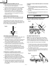
5. If the blade is not 90° to the table, loosen or tighten
(depending on increasing or decreasing the degree)
the hex screw (3) with a 5 mm hex wrench until you
achieve 90°.(Fig. G)
6. The re-loosen the bevel lock handle and reset the
blade at the maximum vertical position, then tighten
the bevel lock handle.
7. Check again to see if the blade is 90° to the table. If
not, repeat step 5.
8. Lastly, check the bevel angle scale. If the pointer
does not read 90°, loosen the screw holding the
pointer and move the pointer so it is accurate at 0°
and retighten the pointer screw.
WARNING
WARNING
1
3
4
6
5