


– 16 –
English
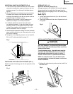
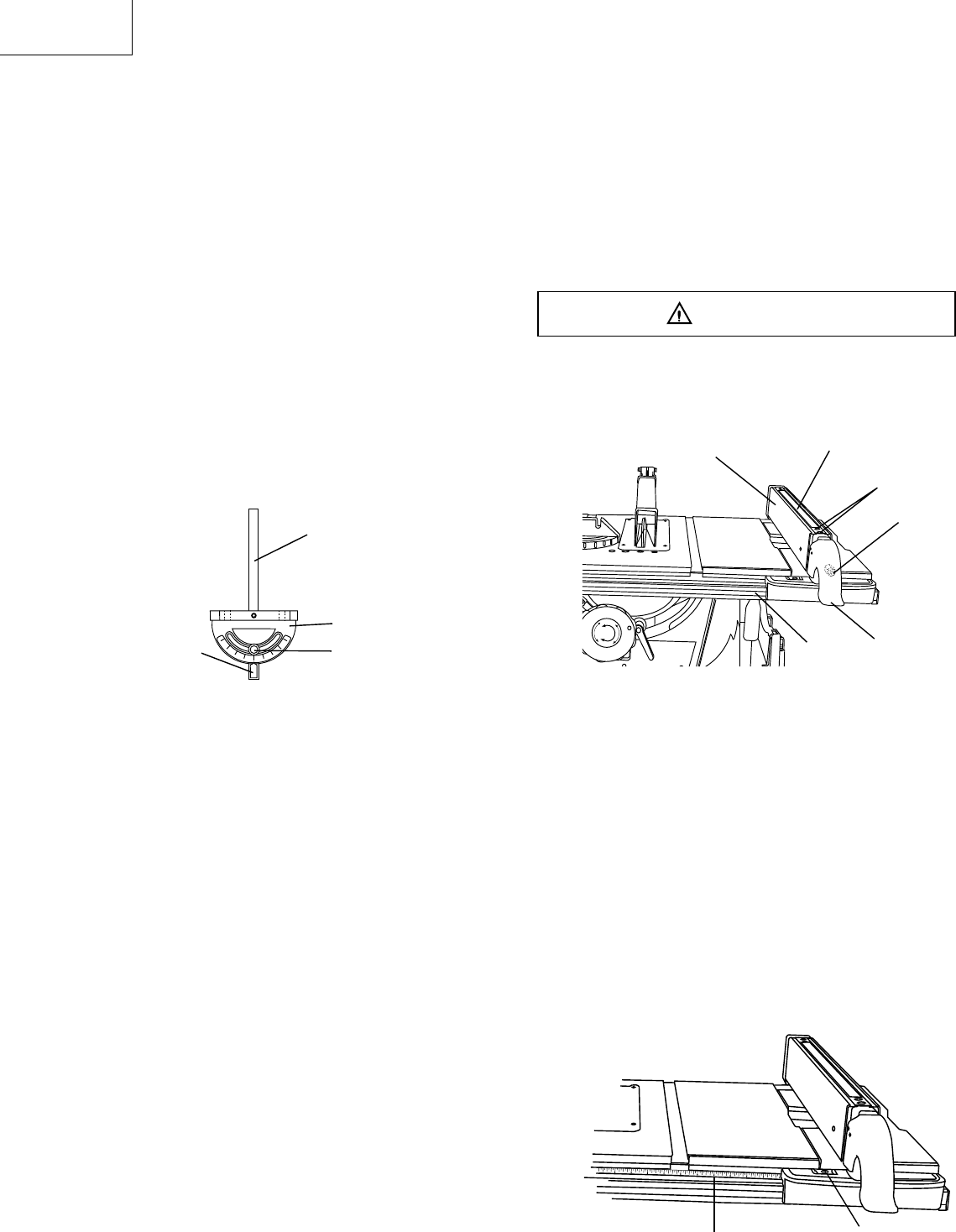
If the fence is loose when the handle is in the locked
position:
1. Move the handle upward to the unlocked position.
Turn the adjusting screw (6) clockwise until the rear
clamp is snug.
2. DO NOT turn the adjusting screw more than 1/4 turn
at a time.
3. Over-tightening the screw will cause the rip fence to
come out of alignment.
Failure to properly align the fence can cause “
kickback” and serious injury could occur.
Fig. N
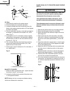
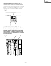
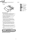
RIP FENCE INDICATOR (FIG. O)
NOTE: The rip fence indicator points to the scale on
the front of the table saw. Measurement shown by the
indicator will provide the user with accuracy up to 1/16
of an inch. Measurement shown is the distance from the
blade to the side of the fence closest to the blade.
1. To check the accuracy, measure the actual distance
(1) to the side of the rip fence. If there is a difference
between the measurement and the indicator, adjust
the indicator as shown next.
2. Loosen the indicator screw (2). Slide the indicator to
the correct measurement position on the scale, then
retighten the screw (2).
Fig. O
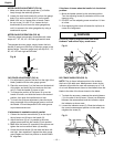
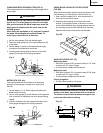
RIP FENCE ADJUSTMENT (FIG. N)
1. For adjustments, position the fence to the right of the
blade, parallel with the miter gauge groove.
2. Place the rear clamp (1) of the fence on the back rail
of the table, and lower the front end over the front
rail (2). Push the handle (3) down to lock.
3. To change the position of the fence, lift up on the
handle to unlock, and slide the fence to the desired
position, then push the handle down to lock.
4. To check the rip fence adjustment, place the fence
along one edge of the miter gauge groove, and lock
the handle. It should be parallel to the miter groove
to provide accurate cuts.
If adjustment is needed to make it parallel:
1. Loosen the two hex wrench bolts (4) on the top of
the rip fence, and lift up on the handle (3).
2. Adjust the fence (5) so it is parallel to the miter
gauge groove and lock the handle (3) into position.
3. Make sure the fence (5) is parallel to the groove and
tighten the two hex wrench bolts (4) securely.
4. Unlock the fence handle (3) and slide the fence left
and right, then reposition it against the miter gauge
groove again and lock into position to double check
its’ alignment.
WARNING
2
1
13
1
2
3
4
6
5
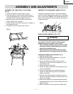
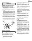
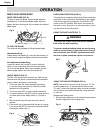
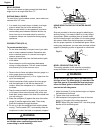
MITER GAUGE ADJUSTMENT (FIG. M)
1. Make sure that the miter gauge bar (1) will slide
freely through the table top grooves.
2. Loosen the lock knob handle (2) and turn the gauge
body (3) to set the pointer (4) at 0º on the scale.
3. Make a 90º cut in a scrap piece of wood. Check
the cut to see if it is 90º. If not, loosen the lock
knob handle (2) and move the miter gauge body
until it is square to the miter gauge bar by using a
combination square.
MITER GAUGE OPERATION (FIG. M)
The miter gauge is accurately constructed with index
stops at 0º, 15º, 30º, 45º, 60º both right and left side.
The operate the miter gauge, simply loosen the lock
handle (2) and move the body of the miter gauge to the
desired angle. The miter gauge body will stop at 0º, 15º,
30º, 45º, 60º both right and left side.
Fig. M
1
3
2
4