


– 15 –
English
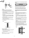
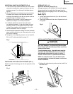
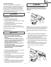
ADDITIONAL BLADE ADJUSTMENTS (Fig. I)
1. If the front and rear measurements are not the same,
remove the combination square and loosen the four
adjusting screws (1) on the top of the table about a
half turn.
2. With a folded piece of cardboard covering the blade
to protect your hands, move the blade and motor
mounting rod carefully to the left or right as much as
needed to align the blade correctly.
3. Tighten the four screws (1) and re-measure, as
described in steps 4 to 9 in the prior section.
4. If sufficient adjustment cannot be made by the
four adjusting screws (1), then also loosen the two
adjusting screws (2) and repeat all previous steps.
Loosen these screws only if necessary at they are
set for accurate 90° and 45° settings.
5. Recheck blade clearance making sure that the blade
does not hit the table insert or other parts when at the
90° and 45° settings.
6. Re-tighten all four adjusting screws (1) and reset the
90° and 45° setting as stated on page 13.
Fig. I
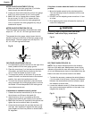
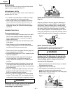
INSTALLING THE PUSH-STICK STORAGE (FIG. J)
Attach the push-stick storage (1) into the right side of the
body shell.
Fig. J
STORAGE (FIG. J, K)
Rip fence and miter gauge (Fig. J)
Storage brackets for the rip fence (3) and miter gauge
(4) are located on the right side of the saw housing.
NOTE:Adjust the miter gauge to 45
0
~60
0
before putting
to the storage.
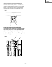
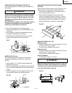
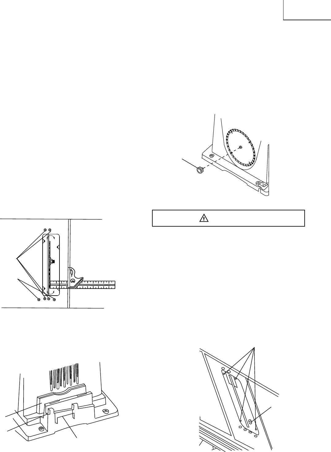
Blade (Fig. K)
1. Loosen and remove the knob (1) on the left side of
the saw housing.
2. Place extra blades onto the arbor. Replace the knob
and tighten.
Fig. K
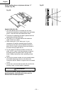
INSTALLING THE TABLE INSERT (FIG. L)
The table insert has been previously installed on
your unit. However, you must verify that the table
insert is flush with the table top surface on all four
corners of the insert.
To aviod serious injury , the table insert must be
level with the table.If the table insert is not flush
with the table, adjust the four bolts (1) with a 4
mm hex. wrench until it is parallel with the table.
NOTE: To raise the insert , turn the hex screws
counterclockwise, to lower the insert, turn the hex
screws clockwise.
1. Replace the table insert by pulling out the hold (2) of
the table insert.
Fig. L
WARNING
1
2
3
4
1
1
1
2