


English
14
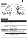
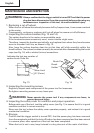
Fig. 8 Fig. 9
Flat hd. screw of more than
15/64" × 19/32" (6 mm × 15)
8-27/64"
(214 mm)
2-3/8" (60 mm)
1-5/64" (27.5 mm)
1-5/64" (27.5 mm)
4-23/32"
(120 mm)
1-49/64"
(45 mm)
15/64"
(6 mm) nut
Vise (B)
Two holes 1/4"
(6.5 mm)
More than 15/64"
(6 mm)
Steel
board
M10 hexagon
socket head bolts
Vise (B)
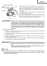
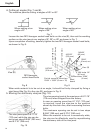
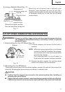
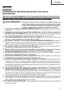
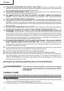
4. Cutting at angles (Fig. 7 and 8).
The machine permits cutting at angles of 45° or 60°
Fig. 7
Loosen the two M10 hexagon socket head bolts on the vise (B), then set the working
surface on the vise-jaw at any angles of 0°, 30° or 45° as shown in Fig. 7.
Upon completion of setting, securely tighten the two M10 hexagon socket head bolts,
as shown in Fig. 8.
When wide material is to be cut at an angle, it should be firmly clamped by fixing a
steel board like Fig. 9 to the vise (B), as shown in Fig. 9.
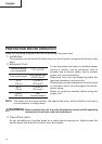
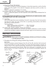
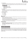
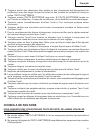
5. Moving the stationary vise-jaw (Fig. 10).
The vise opening is set at the maximum of 6-11/16"
(170 mm) when shipped from the factory.
In case an opening more than 6-11/16" (170 mm)
is required, move the vise-jaw to the position
shown by the chain line, after unscrewing the two
bolts.
The maximum opening can be set in two steps
8-5/64" (205 mm) and 9-7/16" (240 mm).
When the material to be cut is excessively wide,
the vise can be effectively used by repositioning
the stationary side of the vise jaws.
Fig. 10
When setting at an
angle of 0°
When setting at an
angle of 30°
When setting at an
angle of 45°
The vise jaws open to 6-11/16"
(170 mm) while the vise can be
set in two steps 8-5/64" (205 mm)
and 9-7/16" (240 mm)