


Service Clearance, Floor Cutout, and Floor Load Rating
This section specifies the service clearance requirements (a + b) for the
Universal Storage Platform VM storage system, based on the floor load rating
and the clearance (c), and the required floor cutouts for cabling.
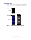
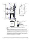
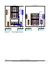
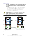
• Figure 2-4 shows the service clearance and floor cutout requirements for
the single-rack configuration.
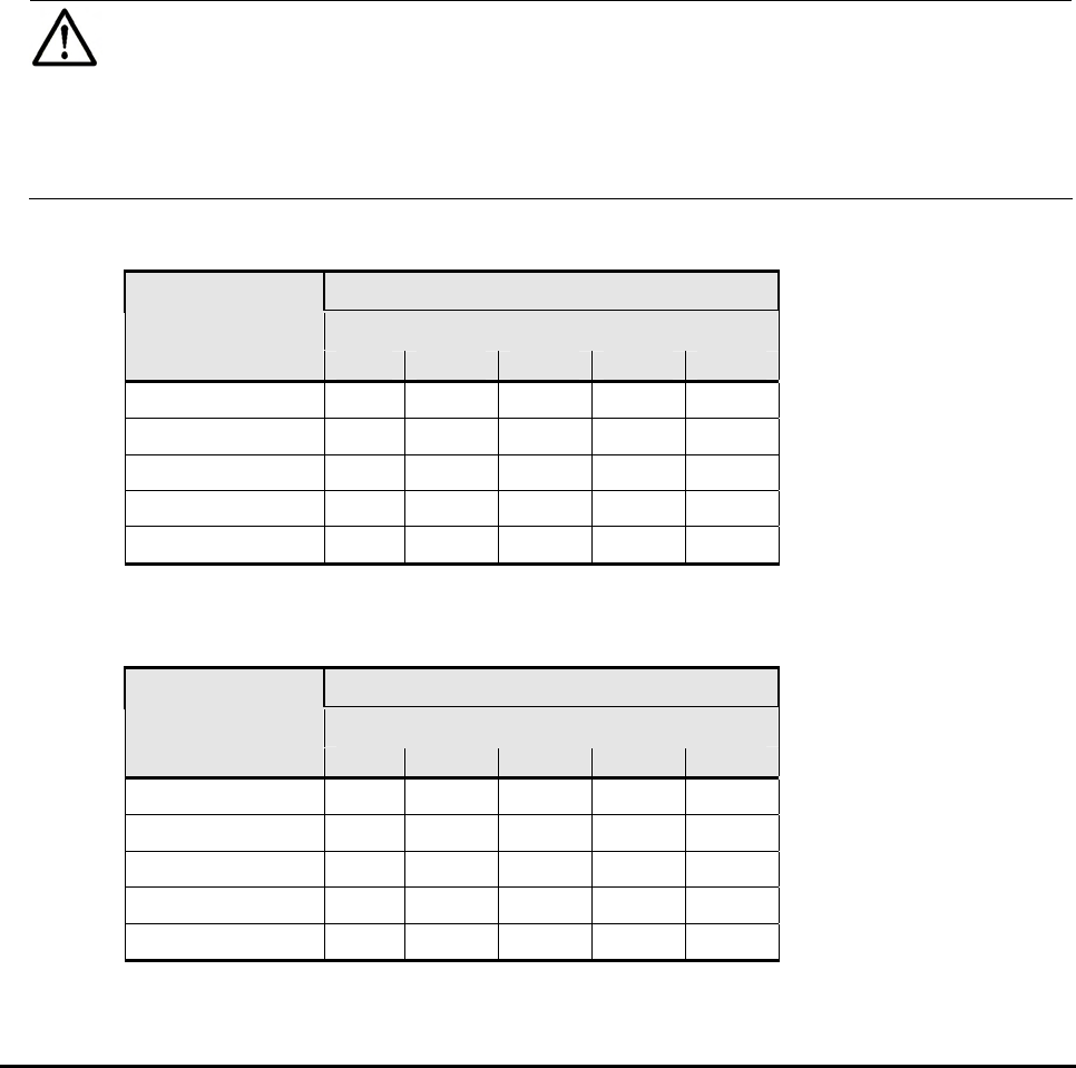
Table 2-3 shows the floor load rating and
clearance requirements for this configuration.
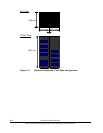
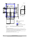
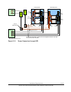
• Figure 2-5 shows the service clearance and floor cutout requirements for
the twin-rack configuration.
Table 2-4 shows the floor load rating and
clearance requirements for this configuration.
Notes:
• For safe and efficient maintenance operations, clearance (c) should be
made as large as possible.
• Actual clearances for installation should be determined after consultin
g
with
the site/facilities manager, as the clearances could vary depending on the
building conditions.
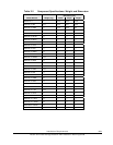
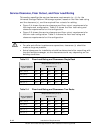
Table 2-3 Floor Load Rating and Clearances: Single Rack
Required Clearance (a+b) m
Clearance (c) m
Floor Load Rating
kg/m
2
(lb/ft
2
)
C=0 C=0.2 C=0.4 C=0.6 C=1.0
500 (102.4) 0.2 0.2 0.2 0.2 0.2
450 (92.2) 0.2 0.2 0.2 0.2 0.2
400 (81.9) 0.2 0.2 0.2 0.2 0.2
350 (71.7) 0.3 0.2 0.2 0.2 0.2
300 (61.4) 0.6 0.4 0.3 0.2 0.2
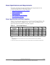
Table 2-4 Floor Load Rating and Clearances: Two Racks
Required Clearance (a+b) m
Clearance (c) m
Floor Load Rating
kg/m
2
(lb/ft
2
)
C=0 C=0.2 C=0.4 C=0.6 C=1.0
500 (102.4) 0.2 0.2 0.2 0.2 0.2
450 (92.2) 0.2 0.2 0.2 0.2 0.2
400 (81.9) 0.2 0.2 0.2 0.2 0.2
350 (71.7) 0.4 0.3 0.2 0.2 0.2
300 (61.4) 0.8 0.6 0.5 0.4 0.2
2-10 Installation Requirements
Hitachi Universal Storage Platform VM Installation Planning Guide