


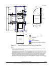

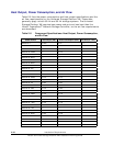
Breaker Configurations
For both racks, AC power is supplied to each power distribution unit (PDU)
from the breaker.
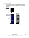
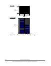
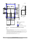
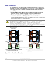
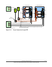
Figure 2-7 and Figure 2-8 show the breaker configurations
for the primary and secondary racks, respectively.
DKC
DKU-R1
DKU-R0
DKC
DKU-R0
Configuration with one disk chassis (DKC-F615I-B2) installed
Regardless of the number of
disk chassis, the number of 20A
breakers is the same.
PDU
(1φ/20A)
PDU
(1φ/20A)
PDU
(1φ/20A)
PDU
(1φ/20A)
30A
breaker
30A
breaker
30A
breaker
30A
breaker
30A
breaker
30A
breaker
30A
breaker
30A
breaker
Configuration with two disk chassis (DKC-F615I-B2) installed
Figure 2-7 Breaker Configurations for the Primary Rack
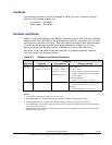
Configuration with one disk chassis (DKC-F615I-B2) installed
PDU
(1φ/20A)
PDU
(1φ/20A)
PDU
(1φ/20A)
30A
breaker
30A
breaker
PDU
(1φ/20A)
PDU
(1φ/20A)
PDU
(1φ/20A)
30A
breaker
30A
breaker
30A
breaker
30A
breaker
Configuration with two disk chassis (DKC-F615I-B2) installed
When adding a disk chassis,
add two 20A breakers.
PDU
(1φ/20A)
PDU
(1φ/20A)
DKU-R2
DKU-R3
DKU-R2
Figure 2-8 Breaker Configurations for the Secondary Rack
Installation Requirements 2-15
Hitachi Universal Storage Platform VM Installation Planning Guide