


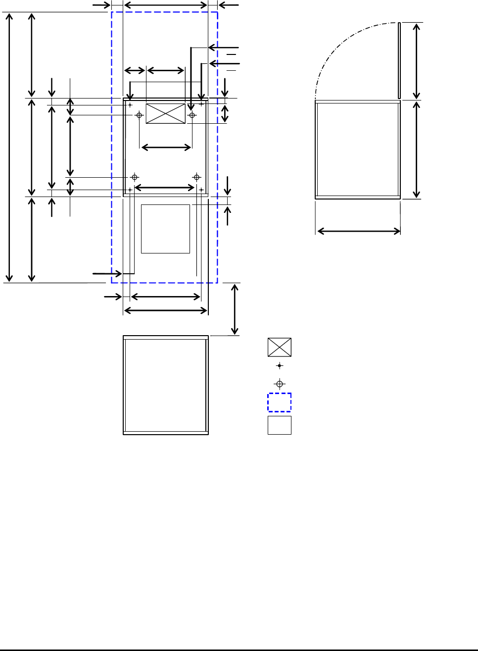
(Unit : mm)
Floor cutout area for cables
Caste
r
Screw jack
Service clearance
G
Grid panel (over 450mm x 450mm)
601
Front
G
DKC615
a *1
B *1
195
65 125
65
835
63 90
74
61.5
457
482
601
c *1
3250
1050
1100
Front
1050.00
575
601
Rear
DKC615
125
200 or more
355
482
215
62
125
1100
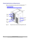
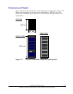
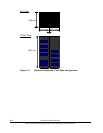
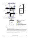
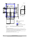
Figure 2-4 Service Clearance and Floor Cutouts: Single Rack
Notes:
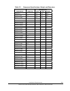
1. Clearance (a+b) depends on the floor load rating and clearance (c). See
Table 2-3 for floor load
rating and clearance requirements.
Leave clearance of 100 mm on both sides of the storage system when the stabilizer plate(s) are to
be attached after the storage system is installed. When storage systems of the same type are to be
installed adjacent to each other, the minimum clearance between the storage systems is 100 mm.
2. Dimensions in parentheses show allowable range of the floor cutout dimensions. Position the floor
cutout in the center of the storage system. The position may be off-center if the cutout allows
smooth entrance of an external cable. Check the relation between the positions of the cutout and
the opening on the bottom plate of the storage rack, and verify that it is within the allowable range.
3. This dimension varies depending on the floor cutout dimensions.
Installation Requirements 2-11
Hitachi Universal Storage Platform VM Installation Planning Guide