


14 307-830
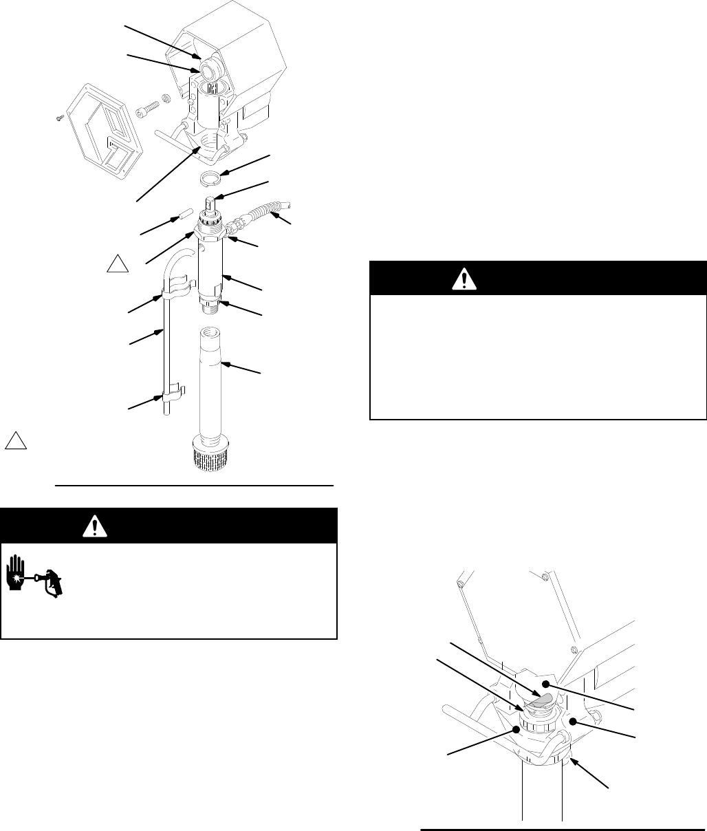
Displacement
Pump
01746B
Fig.
14
222
30
4
49
223
6
50
51
A
Torque
to
80 ft–lb (107 N.m)
3
52
32
76
75
74
1
1
WARNING
INJECTION
HAZARD
T
o reduce the risk of serious bodily
injury
, follow the
Pressure Relief Proce
-
dure W
arning
on page 1
1 before check
-
ing or repairing any part of the spray system.
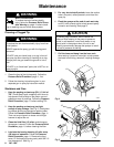
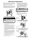
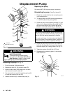
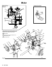
Removing the pump See
Fig. 14.
1.
Flush the sprayer
. Relieve pressure.
2.
Remove the clips (74,76) and drain hose (75).
3.
Hold the intake valve (222) steady with a wrench
and unscrew the suction tube (3).
4.
Use a screwdriver to push the retaining spring (49)
up, and then push out the pin (50).
5.
Loosen the locknut (6). Unscrew the pump (4).
Repairing the pump
See
manual 307–806 for pump repair instructions.
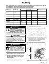
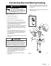
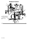
Reinstalling the pump See
Fig. 14 and 15.
1.
Rotate the crankshaft (A) so the connecting rod is
in its lowest position.
2.
The pump piston rod (223) should protrude about
1 in. (25 mm) above the pump cylinder
.
3.
Screw the pump into the bearing housing (51) until
its pin hole is aligned with the connecting rod (52)
pin hole. Insert the pin (50). Position the spring
(49) so it covers the ends of the pin. See Fig. 15.
WARNING
Be sure the retaining spring (49) is firmly and com-
pletely
in the groove of the connecting rod to
prevent
the
pin (50) from working loose due to vibration.
If
the pin works loose, it or other parts could break of
f
due to the force of the pumping action, resulting in
serious
bodily injury
, pump or property damage.
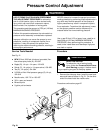
4.
Adjust the pump so the cylinder
’
s top threads are
flush with the face (B) of the bearing housing and
the outlet nipple (32) is straight back. See Fig. 15.
5. T
orque the locknut (6) to 80 ft-lb (107 N.m).
6.
Reassemble the remaining parts, in the reverse
order of removal.
01751A
Fig. 15
51
52
50
49
B
32