


307-830 21
Pressure
Control Adjustment
WARNING
USE
EXTREME CAUTION WHEN PERFORMING
THIS ADJUSTMENT PROCEDURE
to reduce the
risk of a fluid injection injury or other serious bodily
injury
, which can result from component rupture,
electric shock, fire, explosion or moving parts.
This procedure sets the sprayer to 2750 psi (190 bar)
MAXIMUM WORKING PRESSURE.
Perform this procedure whenever the microswitch or
pressure control assembly is reinstalled or replaced.
Improper calibration can cause the sprayer to over
-
pressurize, resulting in component rupture, fire or
explosion. It may also prevent the sprayer from
obtaining the maximum working pressure, resulting in
poor sprayer performance.
NEVER attempt to increase the sprayer
’
s maximum
working pressure by performing these adjustments in
any other way
. Normal operation of the sprayer at
higher pressures may result in component rupture,
fire or explosion. T
o perform this adjustment, howev
-
er
, the sprayer pressure must be
temporarily
in
-
creased above the normal working pressure.
Use a
new
50 foot (15.2 m) spray hose, rated for at
least 3000 psi (210 bar) MAXIMUM WORKING
PRESSURE, when performing this procedure. A
used, under–rated hose could develop a high pres
-
sure leak or rupture.
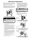
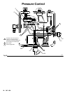
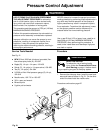
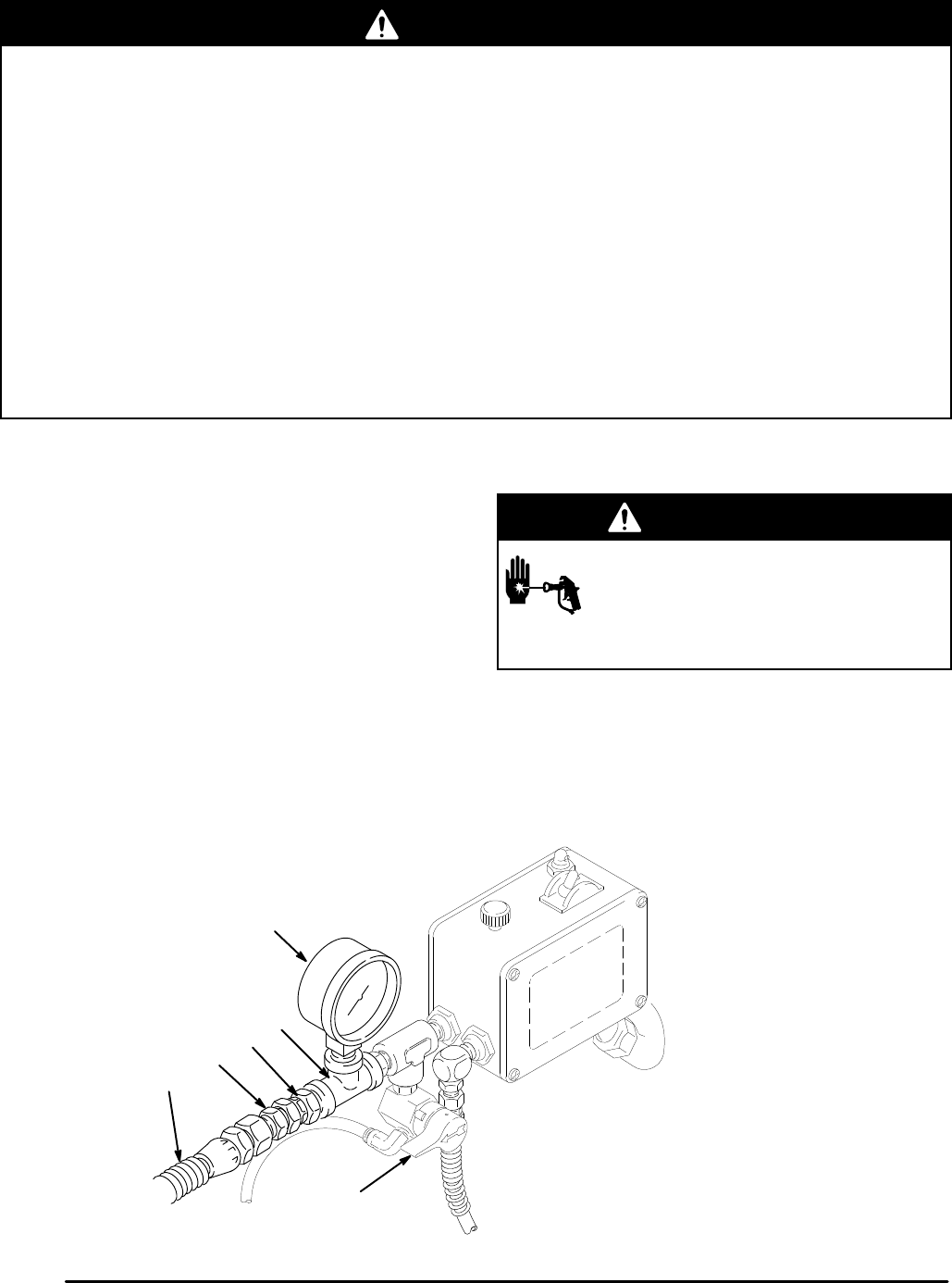
Service Tools Needed
See
Fig. 21.
D
NEW
50 foot, 3000 psi (minimum) grounded, flex
-
ible airless spray hose (A), 223–541
D
Nipple (B), 1/4 npt x 1/4 npsm, 162–453
D
Swivel (C), 1/4 npt(m) x 1/4 npsm swivel, 156–823
D T
ee (D), 1/4 npt(m), 104–984
D
0–5000 psi fluid–filled pressure gauge (E),1/4 npt,
102–814
D
Needle valve, 102–715 or 103–067
D
3/8 in. open end wrench
D
Mineral spirits
D
5 gallon pail and water
Procedure
WARNING
INJECTION HAZARD
T
o reduce the risk of serious bodily
injury
, follow the
Pressure Relief Proce
-
dure W
arning
on page 1
1 before check
-
ing or repairing any part of the spray system.
1.
Remove the old spray hose. Install the new hard
-
ware and hose as shown in Fig. 21. On the other
end of the hose install the needle valve.
Procedure continued on page 22
01315
Fig. 21
A
B
C
D
E
44