


307-830 17
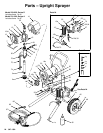
Motor
WARNING
INJECTION HAZARD
T
o reduce the risk of serious bodily
injury
, follow the
Pressure Relief Proce
-
dure W
arning
on page 1
1 before check
-
ing or repairing any part of the spray system.
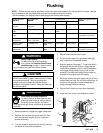
NOTE:
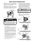
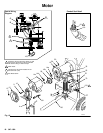
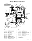
Refer to Fig. 18.
1.
Remove the four screws (13) and front cover (12).
Disconnect the hose (30) and drain hose (80).
2.
Remove the pressure control cover (21). Discon
-
nect the four motor leads.
3.
Unscrew the connector nut (103) at the pressure
control. Swing the conduit (27) away from the
connector.
4.
Remove the conduit seal (18) from around the
wires in the pressure control. Pull the motor leads
through the elbow
, one at a time.
CAUTION
Always pull the motor leads one at a time to avoid
loosening the terminals.
5.
Loosen the nut of the connector (25) at the motor
.
Pull the conduit (27) away from the motor and then
pull the wires through the conduit, one at a time.
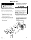
6.
Remove the connector (25) elbow from the motor
,
and then pull the wires through it one at a time.
7.
Remove the screws (42) from the recess of the
drive housing (14). Remove the screws (72) and
washers (54) from the rear of the motor
’
s front end
bell.
8.
Remove the screws (53) and washers (54) from
the rear of the motor
’
s front end bell.
9.
Lightly tap the lower rear of the drive housing (14)
with a plastic mallet to loosen the assembly from
the motor (16). Pull the drive housing assembly of
f
the motor
.
CAUTION
DO NOT drop the gear cluster (56) when removing
the drive housing (14). The gear may stay engaged
in the motor or drive housing.
DO NOT lose the thrust balls (14c, 16b), or allow
them to fall between the gears. The balls, heavily
covered with grease, usually stay in the shaft
recesses, but could become dislodged. If caught
between gears and not removed, the balls will seri
-
ously damage the drive housing. If they are not in
place, the bearings will wear prematurely
.
10.
While supporting the motor to keep the sprayer
from tipping, remove the capscrews (35) which
hold the motor to the cart. Lift the motor of
f the
cart.
11.
Mount the new motor to the cart.
12.
Liberally apply bearing grease to the gear cluster
(56). Be sure the thrusts balls (14c,16b) are in
place.
13.
Place the dark washer (14b) and then the light one
(14a) on the shaft protruding from the big gear in
the drive housing. Align the gears and push the
new drive housing straight onto the motor and its
locating pins.
14.
Continue reassembling the sprayer
. Follow the
NOTE and W
ARNING, below
.
NOTE:
Use a turning motion on the conduit when
feeding wires through it.
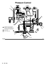
WARNING
All wires connected to the over-pressure switch (C)
and the pressure switch (D) must be insulated at
the terminals to reduce the risk of electric shock if
someone touches these parts when the power is
on. When installing the new pressure control, be
sure these terminals are covered with shrink tubing
or electrical tape.