


OM-927 Page 19
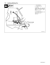
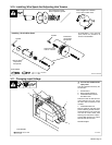
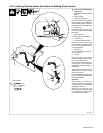
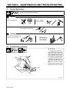
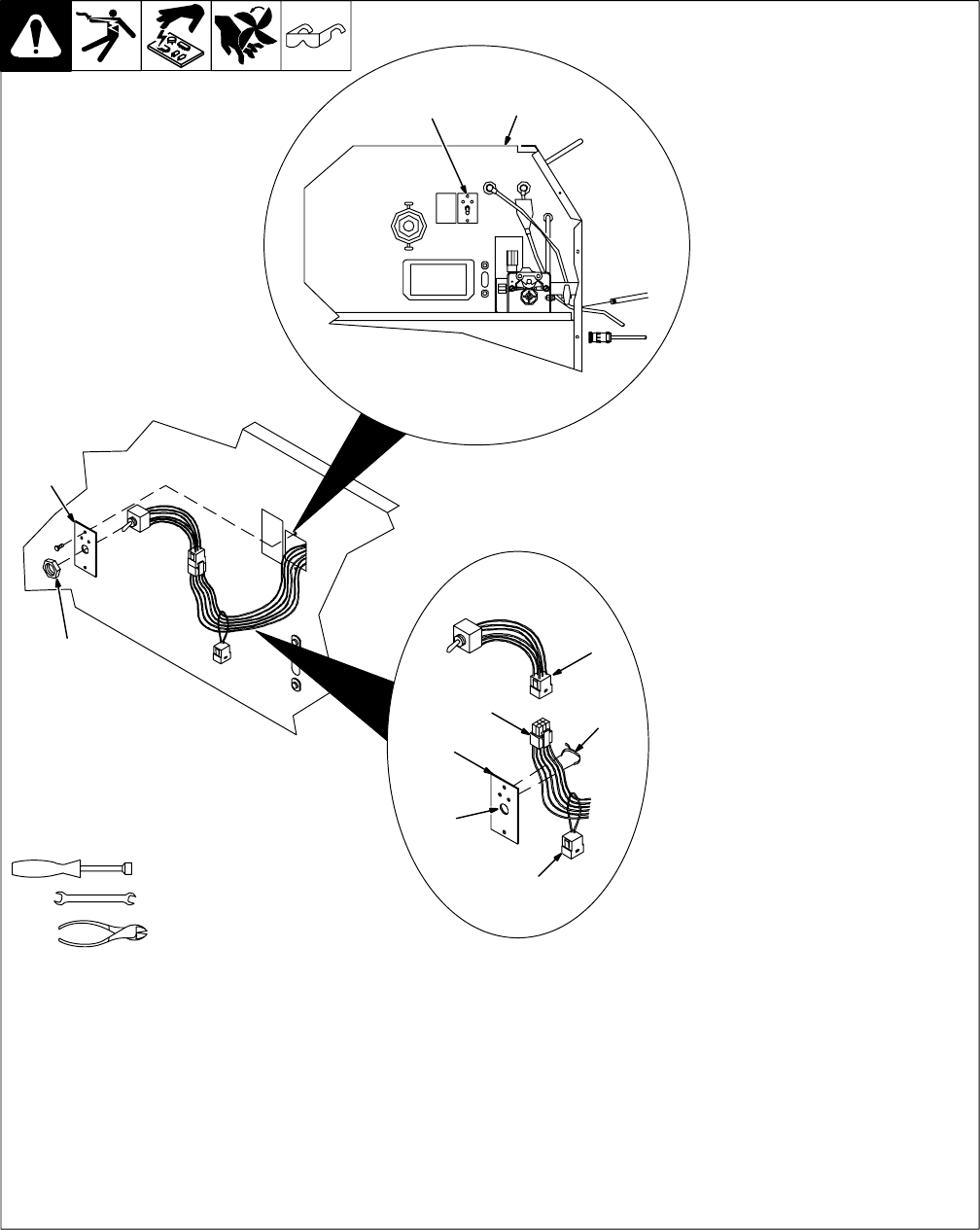
3-15. Installing Optional Spool Gun Switch In Welding Power Source
802 936-A
Tools Needed:
1/4 in
9/16 in
Y Turn Off unit, and disconnect
input power.
1 Welding Power Source Center
Baffle
2 Switch Location
3 Switch Mounting Plate
Remove 2 screws securing switch
mounting plate to center baffle. Pull
switch mounting plate to pull wiring
harness through center baffle hole.
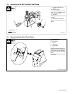
4 Plastic Plug
Remove and discard plastic plug
from center hole in switch mounting
plate panel.
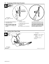
5 Nylon Cable Tie
Cut and discard nylon cable tie.
6 Jumper Plug
7 Wiring Harness Switch Plug
Remove jumper plug from wiring
harness switch plug. Retain jumper
plug by placing looped lead over
unit wiring harness.
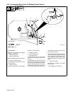
8 Switch Plug
Connect switch plug to wiring har-
ness switch plug.
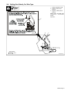
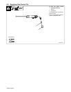
9 Jam Nut
Remove top jam nut from switch
(switch is equipped with two nuts, a
jam nut and a backing nut).
Insert switch shaft through switch
mounting plate. Switch should be
positioned so lead with resistor is
facing down.
Secure switch to plate with jam nut.
Tighten jam nut enough to keep
switch from rotating.
Push wiring harness back through
hole, and reinstall switch mounting
plate to center baffle.
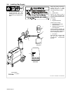
Operation:
Place switch in On position for
spool gun operation. Place switch
in Off position for wire feeder/MIG
(GMAW) gun operation.
When spool gun switch is in On
position, spool gun wire feed speed
is controlled by welding power
source Wire Speed control.
3
9
4
3
6
5
8
7
2
1