


OM-927 Page 23
Ref. 199 208-B
3/8”
(9.5 mm)
—
5/58
5/52
5/100
5/72
5/60
5/66
5/44
5/30
—
—
—
—
—
—
—
1/4”
(6.4 mm)
—
4/48
4/34
5/100
4/62
4/52
4/52
4/36
5/30
6/90
6/76
6/70
6/78
6/72
6/100
6/84
1/8”
(3.2 mm)
3/46
3/34
3/20
4/80
3/42
3/40
2/20
2/10
3/10
5/82
5/64
5/66
4/68
4/60
4/88
4/84
14 ga.
(2.0 mm)
3/46
3/32
3/18
3/68
3/40
3/36
2/14
2/4
—
4/70
4/56
4/40
2/68
2/58
2/80
2/70
16 ga.
(1.6 mm)
2/18
2/14
2/12
2/36
2/24
2/20
1/12
1/0
—
3/50
3/46
3/32
1/56
—
1/70
—
18 ga.
(1.2 mm)
2/18
2/12
2/12
2/36
2/24
2/16
1/12
—
—
3/46
3/46
3/28
—
—
—
—
20 ga.
(0.9 mm)
2/18
2/10
—
1/16
1/16
2/14
—
—
—
3/42
3/40
2/24
—
—
—
—
22 ga.
(0.8 mm)
2/16
—
—
1/16
1/16
—
—
—
—
3/42
2/32
—
—
—
—
—
3/16”
(4.8 mm)
4/74
4/44
4/34
4/80
4/62
4/50
3/46
3/20
4/20
5/86
5/68
5/66
5/72
5/66
5/88
5/84
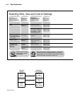
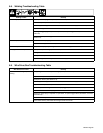
VOLTAGE
1
2
3
4
5
6
10
20
30
40
50
60
70
80
90
WIRE SPEED
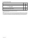
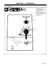
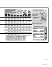
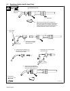
Wire Size Stock No.
V−Grooved .024”,.030”/.035”
202925
.024”,.045”
407230−004
V−Knurled .030”/.035”
193330
.039”/.045”, .056”2”/ 1/16”
193331
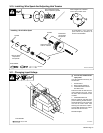
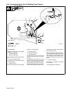
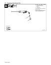
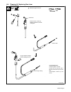
A) Nozzle
.500 orf flush #169 715
B) Tips
.023/0.6 mm #087 299
.030/0.8 mm #000 067
.035/0.9 mm #000 068
.045/1.1 mm #000 069
C) Contact Tip Adapter #169 716
D) Retaining Ring #170 470
E) Head Tube #169 718
Liners
.023/.025 #194 010
.030/.035 #194 011
.035/.045 #194 012
M−10 Consumables
DriveRolls
A
B
C
D
E
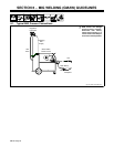
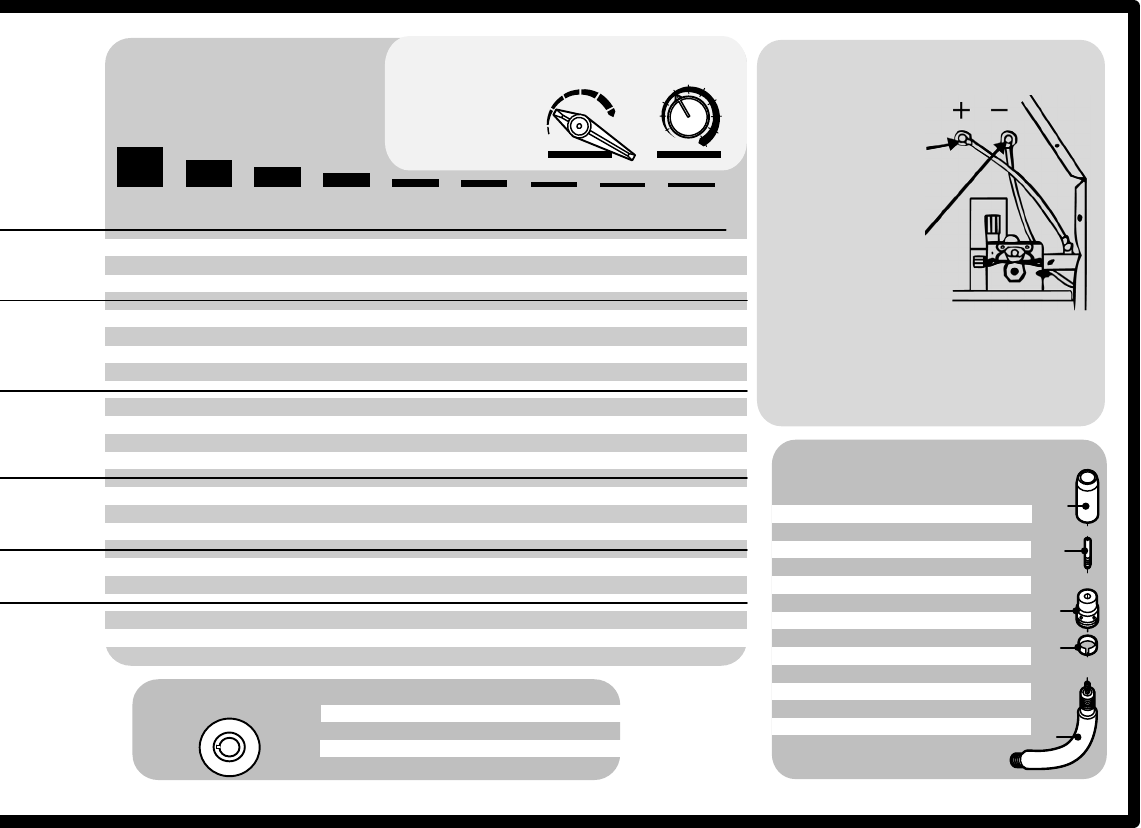
Changing Polarity
Example: 2/40 =
To read settings:
Number on left of slash
is voltage,numberon
right of slash is wire
speed.“—” means
not recommended.
#199208B
Select Voltage and Wire Speed Based
on Thickness of Metal Being Welded
SETTINGS ON THIS CHART ARE STARTING
VALUES ONLY AND ARE ON 230 INPUT
LINE VOLTAGE. SEE OWNERS MANUAL
FOR MORE INFORMATION.
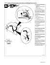
Wire Drive Assembly
Lead To Positive (+)
Output Terminal
Work Clamp Lead
To Negative (−)
Output Terminal
Electrode Negative (DCEN): Reverse lead
connections at terminals from that shown
for gasless flux cored wires (FCAW). Drive
assembly becomes negative.