


OM-927 Page 31
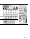
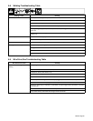
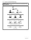
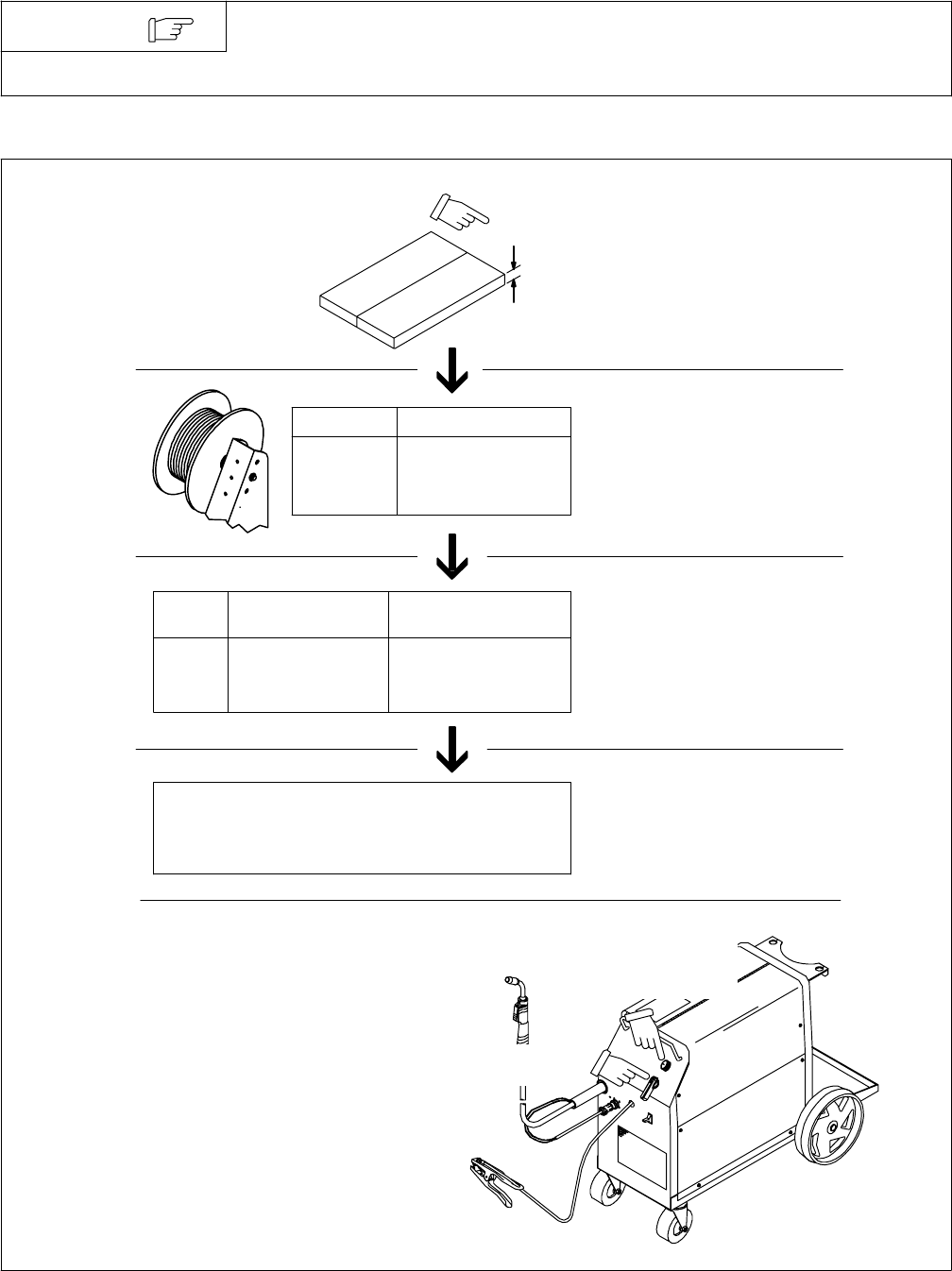
6-2. Typical MIG Process Control Settings
These settings are guidelines only. Material and wire type, joint design, fitup,
position, shielding gas, etc. affect settings. Test welds to be sure they comply to
specifications.
NOTE
3.5 x 125 A = 437 ipm
2 x 125 A = 250 ipm
1.6 x 125 A = 200 ipm
30 − 90 A
40 − 145 A
50 − 180 A
Convert Material
Thickness to
Amperage (A)
Material thickness determines weld
parameters.
.035 in
Recommendation
Wire Speed
(Approx.)
802 600-C
1/8 or 0.125 in
(0.001 in = 1 ampere)
0.125 in = 125 A
Wire Size Amperage Range
0.023 in
0.030 in
0.035 in
Select Wire Size
Wire
Size
0.023 in
0.030 in
0.035 in
3.5 in per ampere
2 in per ampere
1.6 in per ampere
Select Wire Speed
(Amperage)
125 A based on 1/8 in
material thickness
ipm = inches per minute
Low voltage: wire stubs into work
High voltage: arc is unstable (spatter)
Set voltage midway between high/low voltage
Select Voltage
Wire speed (amperage)
controls weld penetration
(wire speed = burn-off rate)
Voltage controls height and width
of weld bead.