


OM-474 Page 21
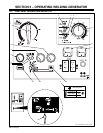
SECTION 6 – OPERATING AUXILIARY EQUIPMENT
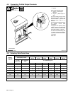
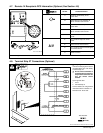
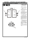
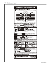
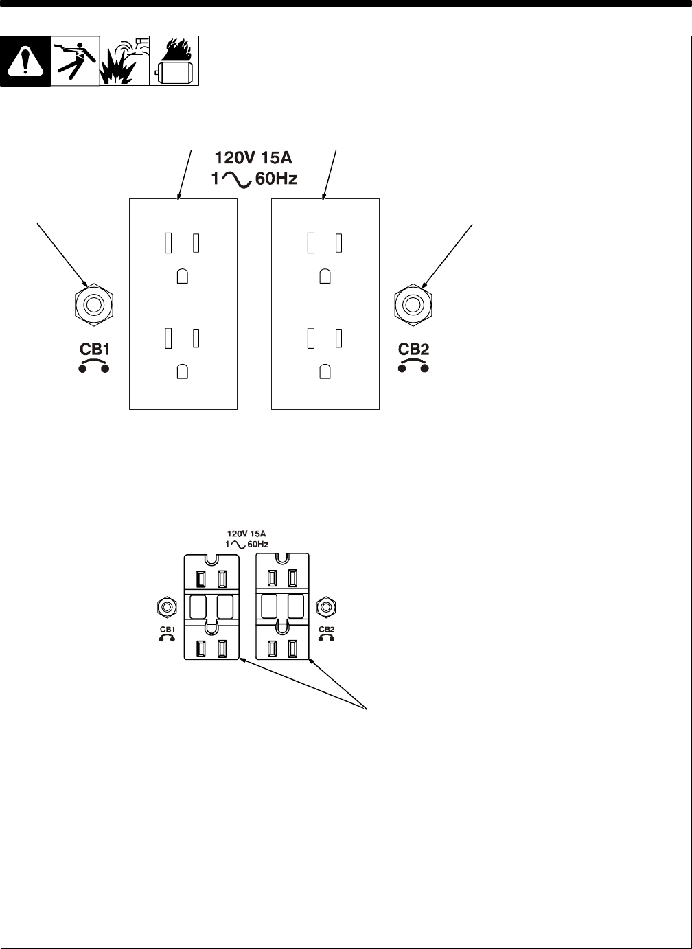
6-1. 120 Volt Duplex And Optional GFCI Receptacles
Ref. ST-191 898
Y If unit does not have GFCI re-
ceptacles, use GFCI-pro-
tected extension cord.
1 120 V 15 A AC Receptacle
RC1
2 120 V 15 A AC Receptacle
RC2
3 120 V 15 A AC GFCI Recep-
tacles GFCI1 And GFCI2
(Optional)
Receptacles supply 60 Hz single-
phase power at weld/power speed.
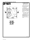
4 Circuit Breaker CB1
5 Circuit Breaker CB2
CB1 protects RC1/GFCI1 and CB2
protects RC2/GFCI2 from over-
load. If CB1 or CB2 opens, the re-
ceptacle does not work. Press but-
ton to reset circuit breaker.
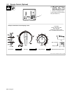
. If a circuit breaker continues to
open, contact a Factory
Authorized Service Agent.
If a ground fault is detected, the
GFCI Reset button pops out and
the circuit opens to disconnect the
faulty equipment. Check for dam-
aged tools, cords, plugs, etc. con-
nected to the receptacle. Press but-
ton to reset receptacle and resume
operation.
. At least once a month, run en-
gine at weld/power speed and
press Test button to verify
GFCI is working properly.
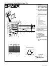
Maximum output from each duplex
receptacle is 1.8 kVA/kW, and 3
kVA/kW from all receptacles.
Auxiliary power is not affected by
weld output.
EXAMPLE: If 15 A is drawn from
RC1, only 10 A is available at RC2:
(120 V x 15 A) + (120 V x 10 A) = 3.0
kVA/kW
12
4
5
3