


OM-474 Page 31
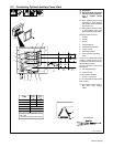
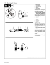
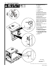
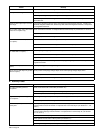
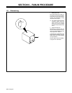
7-8. Inspecting And Cleaning Optional Spark Arrestor Muffler
Ref. ST-191 898 / ST-162 256
Y Stop engine and let cool.
1 Spark Arrestor Muffler
2 Cleanout Plug
Remove plug and remove any dirt
covering cleanout hole.
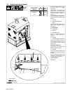
3 Exhaust Pipe
Start engine and run at idle speed to
blow out cleanout hole. If nothing
blows out of hole, briefly cover end
of exhaust pipe with fireproof
material.
Y Stop engine and let cool.
Reinstall cleanout plug.
Tools Needed:
3
2
1
3/8 in
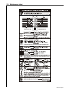
7-9. Troubleshooting
A. Welding
Trouble Remedy
No weld output. Check control settings.
Place optional Output (Electrode) Control switch in On (Hot) position, or move switch to Remote posi-
tion and connect remote contactor to Remote 14 receptacle RC3 or terminal strip 3T (see Sections
4-7, 4-8, and 5-1).
Check and secure connections to optional Remote 14 receptacle RC3 or terminal strip 3T (see
Sections 4-7 and 4-8).
Disconnect equipment from 120 volt ac receptacles during start-up.
Have Factory Authorized Service Agent check brushes and slip rings, and field current regulator board
PC1.
Erratic weld output. Check and tighten connections inside and outside unit.
Use dry, properly-stored electrodes.
Remove excessive coils from weld cables.
Be sure connection to work piece is clean and tight.
Have Factory Authorized Service Agent check brushes and slip rings.
Low or high weld output. Check control settings.
Place optional Process switch in correct position (see Section 5-1).
Check engine weld/power speed, and adjust if necessary (see Section 7-5).