


OM-478 Page 23
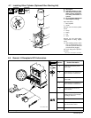
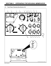
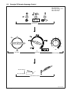
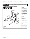
5-2. Description Of Standard Controls (See Section 5-1)
. This unit has a max OCV control circuit
that resets the Amperage/Voltage Con-
trol to maximum when the arc breaks.
When an arc is struck, weld output con-
trol returns to the front panel or remote
control setting. The Amperage/voltage
Control adjusts amperage only when
welding and does not adjust open-circuit
voltage (see item 24, Max OCV On/Off
switch).
1 Voltmeter
2 Ammeter
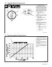
3 Ampere Range Switch
Y Do not switch under load.
Use switch to select one of five ampere
ranges. Use the lower four ranges for CC
welding and the highest range for CV/DC
welding. In each CC range, the upper number
is for CC/DC and the lower number is for CC/
AC. For most welding applications, use the
lowest amperage range possible to help pre-
vent arc outages.
4 Amperage/Voltage Control
Control adjusts amperage within range se-
lected by Ampere Range switch. Weld output
would be 235 A DC with controls set as shown
(50% of 140 to 330 A).
5 Ether Starting Aid Switch
(Optional)
Y Do not use Ether if engine is running.
Push switch up and release while cranking
engine to release ether.
6 Check Battery Light (Optional)
Stop engine and check battery if light goes on
while charging.
7 Battery Charge/Jump Start Selector
Switch (Optional)
Use switch to select battery jump start or
charging output (see Section 7).
8 Battery Charge Voltage Selector Switch
(Optional)
Place switch in position matching voltage of
battery being charged or jump started (see
Section 7).
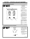
9 Amperage/Voltage Control Switch
Use switch to select front panel or remote am-
perage control (see Section 5-3).
For front panel control, place switch in Panel
position. For remote control, place switch in
Remote position and connect remote control
to Remote 14 receptacle or terminal strip 3T
(see Sections 4-8 and 4-9).
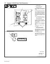
10 CC/CV Selector Switch
Use switch to select type of weld output. Use
CC for Stick (SMAW) welding and Air Carbon
Arc Cutting. Use CV for wire feed processes
(MIG, FCAW). If using CV, place Ampere
Range switch in maximum position. To en-
sure wire feeder reliability and improve
arc starting, unit does not run at idle speed
when operated in CV mode.
. Place CC/CV switch in CC position when
using auxiliary power plant.
11 Output (Contactor) Switch
Use switch to control remote contactor con-
nected to receptacle RC3 or terminal strip 3T
(see Sections 4-8 and 4-9).
12 Service Engine Air Cleaner Light
Service engine air cleaner if light goes on (see
Section 8-2).
13 Engine Control Switch
Use switch to start engine, select engine
speed, and stop engine.
In Run position, engine runs at weld/power
speed. In Run/Idle position, engine runs at
idle speed at no load and weld speed with load
applied. Turn to run position if using auxiliary
power plant. Unit does not run at idle speed
when operated in CV mode.
To Start: turn Engine Control switch to Start
position. Release switch when engine starts.
. If the engine does not start, let engine
come to a complete stop before attempt-
ing restart.
To Stop: turn Engine Control switch to Off
position.
14 Check Engine Belt Light
Light goes on and engine stops if engine alter-
nator is not working. Check engine belt (see
Section 8-8).
15 Service Compressor Air Cleaner Light
Service compressor air cleaner if light goes
on (see Section 8-2).
16 Fuel Gauge
17 Air Tank Moisture Drain Control
Before starting engine each day, pull control
out to drain moisture from air tank.
Push control in to close valve before
operating unit.
18 Battery Ampere Gauge
Use gauge to check amperage output to the
battery. The gauge reads near 0 (zero) when
the engine is running. If gauge is at a negative
number, the battery is discharging. Stop en-
gine, and do not run until problem is fixed.
19 Air Pressure Gauge
Use gauge to check pressure in air storage
tank.
20 Oil Pressure Gauge/Switch
Use gauge/switch to check oil pressure. Nor-
mal operating pressure is about 50 psi (345
kPa). Engine stops if oil pressure is below 22
psi (152 kPa).
21 Engine Hour Meter
22 Oil Temperature Gauge/Switch
Use gauge/switch to check oil temperature.
Normal operating temperature is about 225°F
(107° C). Engine stops if oil temperature ex-
ceeds 265° F (129° C).
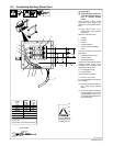
23 Output Selector Switch
Y Do not switch under load.
Use switch to select polarity of weld output.
For Direct Current Electrode Negative
(DCEN), use Electrode Negative position.
For Direct Current Electrode Positive
(DCEP), use Electrode Positive position. For
alternating current (AC), use AC position.
Use Jump Start/Battery Charge position to
turn on output at Jump Start/Battery Charge
receptacle (see Section 7).
24 Max OCV On/Off Switch
Use switch to disable max OCV control cir-
cuit. Place switch in On position for most
welding processes (see max OCV note at be-
ginning of this section).
. If max OCV switch is in Off position, turn
Amperage/Voltage control to max for full
output from optional auxiliary power
plant.