


OM-493 Page 12
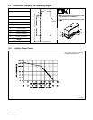
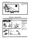
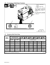
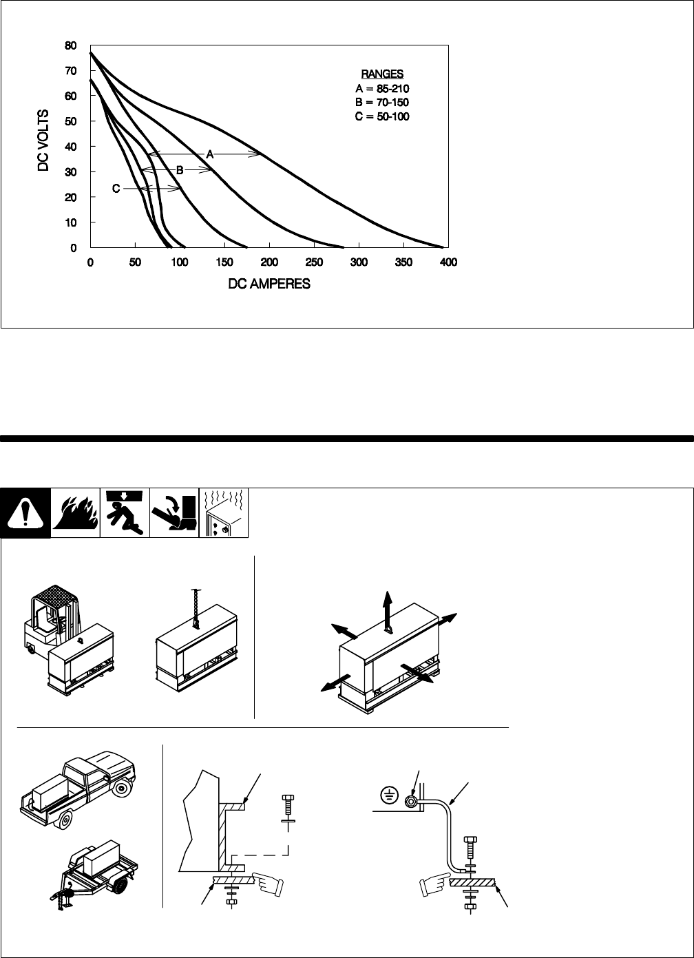
3-6. Volt-Ampere Curve
ST-191 555
The volt-ampere curve shows the
minimum and maximum voltage
and amperage output capabilities of
the welding generator. Curves of all
other settings fall between the
curves shown.
SECTION 4 – INSTALLATION
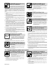
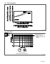
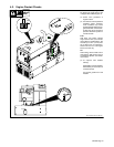
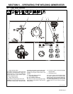
4-1. Installing Welding Generator
install1 12/99 – Ref. ST-800 652 / Ref. ST-800 477-A / ST-158 936-A / S-0854
Y Do not weld on base. Weld-
ing on base can cause fuel
tank fire or explosion. Bolt
unit down using holes pro-
vided in base.
Y Always ground generator
frame to vehicle frame to pre-
vent electric shock and static
electricity hazards.
1 Generator Base
2 Metal Vehicle Frame
3 Equipment Grounding
Terminal
4 Grounding Cable
Use #10 AWG or larger insulated
copper wire.
Y If unit does not have GFCI re-
ceptacles, use GFCI-
protected extension cord.
1
2
Electrically bond genera-
tor frame to vehicle frame
by metal-to-metal contact.
GND/PE
3
4
2
OR
OR
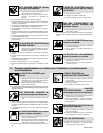
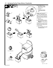
18 in
(460 mm)
18 in
(460 mm)
18 in
(460 mm)
18 in
(460 mm)
18 in
(460 mm)
OR
Movement Airflow Clearance
Location
Grounding
Y Do not lift unit from end.