


OM-493 Page 18
SECTION 6 – OPERATING AUXILIARY EQUIPMENT
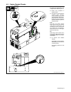
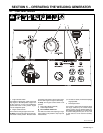
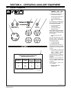
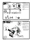
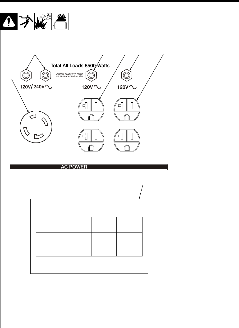
6-1. Standard Receptacles
Ref. ST-192 519 -A
Y If unit does not have GFCI re-
ceptacles, use GFCI-
protected extension cord.
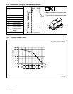
. Auxiliary power decreases as
weld current increases.
Set Fine Adjust control R1 at 10
for full auxiliary power.
1 240 V 30 A AC Receptacle
RC1
RC1 supplies 60 Hz single-phase
power at weld/power speed. Maxi-
mum output is 7.2 kVA/kW.
2 120 V 20 A AC Duplex
Receptacle RC2
3 120 V 20 A AC Duplex
Receptacle RC3
RC2 and RC3 supply 60 Hz single-
phase power at weld/power speed.
Maximum output from RC2 or RC3
is 2.4 kVA/kW.
4 Circuit Breakers CB1 and
CB2
CB1 and CB2 protect RC1 from
overload. If CB1 or CB2 opens,
RC1 does not work. 120 volts may
still be present at RC1.
5 Circuit Breaker CB3
6 Circuit Breaker CB4
CB3 protects RC2 and CB4 pro-
tects RC3 from overload. If a circuit
breaker opens, the receptacle does
not work.
. Press button to reset circuit
breaker. If breaker continues to
open, contact Factory
Authorized Service Agent.
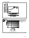
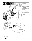
Combined output of all receptacles
limited to 8.5 kVA/kW rating of the
generator.
EXAMPLE: If 20 A is drawn from
each 120 V duplex receptacle, only
13 A is available at the 240V
receptacle:
2 x (120 V x 20 A) + (240 V x 15 A)
= 8.4 kVA/kW
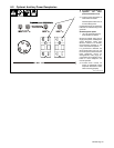
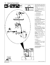
7 Auxiliary Power While
Welding Label
456
1
S-166 360-A
See Owner’s Manual for additional information.
Weld Current
In Amperes
Total Power
120V
210
140
90
1000
4300
6000
36
50
8
240V
18
25
4
WITH FINE ADJUST SET AT 10
In Watts
Receptacle Receptacle
SIMULTANEOUS WELDING AND POWER
7
Amperes Amperes
2
3