


OM-355 Page 9
SECTION 2 – INSTALLATION
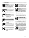
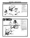
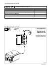
2-1. Included with Your Unit
1 12 ft (3.7 m) Work Cable
With Clamp And
Quick-Connect
2 150 Amp TIG Torch with
12-1/2 ft (3.8 m) Cable
3 Electrode Holder and
Quick-Connect
4 Gas Hose
5 Gas Regulator
6 RFCS-14 Foot Control with
20 ft (6 m) Cable
7 8 ft (2.4 m) Primary Cord
. Some assembly is required.
For options and accessories see
back of book or contact your dis-
tributor.
1
2
3
4
5
7
6
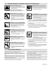
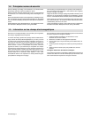
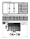
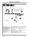
2-2. Selecting A Location
1 Lifting Eye
2 Lifting Forks
Use lifting eye or lifting forks to
move unit.
If using lifting forks, extend forks
beyond opposite side of unit.
3 Rating Label
Use rating label to determine input
power needs.
4 Line Disconnect Device
Locate unit near correct input pow-
er supply.
Position unit so air can circulate.
For information about sources of
high-frequency see Section 6.
For carts and caster kits see back
of book or contact your distributor.
Y Special installation may be
required where gasoline or
volatile liquids are present –
see NEC Article 511 or CEC
Section 20.
1
2
Movement
ST-802 238
4
18 in (460
mm)
Location And Airflow
OR
18 in (460
mm)
18 in
(460 mm)
3
18 in (460
mm)