


OM-355 Page 16
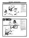
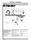
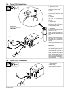
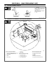
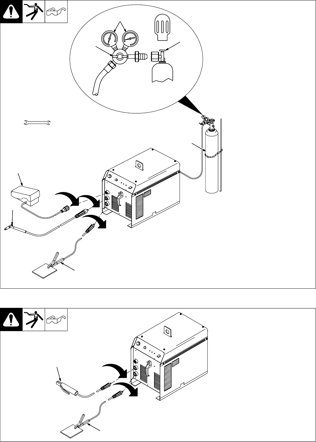
3-4. Typical TIG Connections
ST-802 238
1 Remote Foot Control
A customer supplied remote finger-
tip control may also be used.
2 Torch
3 Work Clamp
Connect remote control, torch, and
work clamp to receptacles as
shown.
4 Cylinder
Chain or secure cylinder to running
gear, wall, or other stationary
support.
5 Cylinder Valve
Open valve slightly so gas flow
blows dirt from valve. Close valve.
6 Regulator/Flow Gauge
Install so face is vertical.
7 Flow Adjust
Typical flow rate is 20 cfh (cubic feet
per hour) (9.4 L/min).
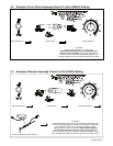
NOTE: After activating remote con-
trol, 0.3 seconds of gas preflow will
begin.
Application:
Preflow is used to purge the imme-
diate weld area of atmosphere.
Preflow also aids in consistent arc
starting.
NOTE: When remote control is
released, gas continues to flow for
18 seconds
Application:
Postflow is required to cool tung-
sten and weld, and to prevent con-
tamination of tungsten and weld. In-
crease postflow time if tungsten or
weld are dark in appearance.
NOTE: Both preflow and postflow
are preset and are not adjustable.
NOTE: When AC welding, the bal-
ance control is preset at 60% elec-
trode negative (EN), and 40% elec-
trode positive (EP).
5
6
7
Tools Needed:
5/8, 1-1/8 in
4
1
2
3
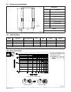
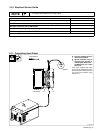
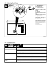
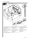
3-5. Typical Stick Connections
ST-802 238
1 Electrode Holder
2 Work Clamp
Connect electrode holder and work
clamp to receptacles as shown.
1
2