


OM-355 Page 12
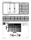
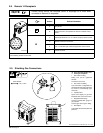
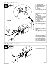
2-8. Remote 14 Receptacle
Remote control device has complete control of amperage at all times when
connected to Remote 14 receptacle.
NOTE
Socket* Socket Information
A 24 volts DC.
B Contact closure to A completes 24 volts DC contactor control
circuit.
C Command reference; 0 to +10 volts DC output to remote control.
AJ
B
K
I
L
NH
D Remote control circuit common.
C
L
NH
D
M
G
E
F
A
E 0 to +10 volts DC input command signal from remote control.
E
ST-802 238
K Chassis common.
*The remaining sockets are not used.
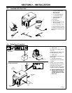
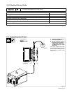
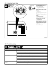
2-9. Shielding Gas Connections
Ref. ST-802 238 / Ref. ST-802 258 / Ref. ST-157 858
Y Turn Off power before con-
necting to receptacle.
1 Gas Valve In Fitting
Fitting has 5/8-18 right-hand
threads.
Located on rear of unit.
2 Gas Valve Out Fitting
Gas connection is integrated into
the Electrode weld output terminal
by means of a flow-through type
connector.
3 Cylinder Valve
Open valve slightly so gas flow
blows dirt from valve. Close valve.
4 Regulator/Flow Gauge
Connect regulator/flow gauge to
gas cylinder.
Connect gas hose to gas in fitting.
5 Flow Adjust
Typical flow rate is 20 cfh (cubic feet
per hour).
5
2
4
1
5/8, 1-1/8 in
Tools Needed:
3