


OM-1581 Page 10
SECTION 3 – INSTALLATION
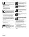
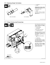
Be sure that contact tip, liner, and drive rolls are correct for wire size and type. See
Section 5 to change parts as needed. See Section 7 for list of other available
contact tips.
NOTE
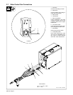
Review Section 3-1 through Section 3-4 to determine how equipment will be connected. Air-cooled models are shown
in Section 3-1 through Section 3-4. For water-cooled models, supplied water hoses must be connected from wire feed-
er to coolant supply.
Read entire Section 3 before installing equipment.
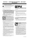
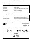
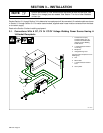
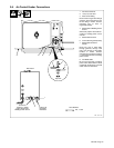
3-1. Connections With A CC, CV Or CC/CV Voltage Welding Power Source Having A
14-Socket Receptacle
1 Constant Current (CC),
Constant Voltage (CV) Or
Constant Current/Constant
Voltage (CC/CV) Welding
Power Source
2 115 VAC/Contactor Control
14-Pin Plug
3 Workpiece
4 Voltage Sensing Lead
Connect lead to workpiece for CC
welding only.
5 Gun
6 Wire Feeder
7 115 VAC/Contactor Control
Cord
8 Gas Cylinder
151 774-B
1
2
3
4
5
6
7
8