


OM-1581 Page 17
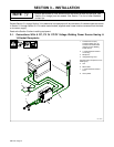
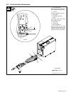
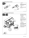
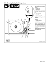
3-10. Adjusting Contact Tip Position
1
3
2
4
1 Contact Tip
2 Nozzle
Adjusting barrel changes contact
tip location from 1/16 in (1.6 mm)
out beyond end of nozzle to 1/4 in
(6.3 mm) inside nozzle.
3 Jam Nut
4 Barrel
To change contact tip location,
loosen jam nut, and turn barrel.
Tighten jam nut.
150 434 / Ref. 150 431
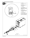
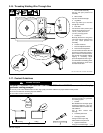
1
2
4
3
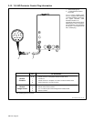
Air-Cooled ModelWater-Cooled Model
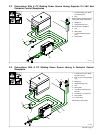
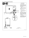
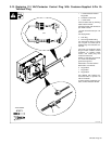
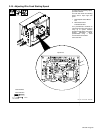
3-11. Voltage Sensing Lead Connections
Unit is factory set for constant volt-
age (CV) welding. To set unit for
constant current (CC) welding,
proceed as follows:
1 Terminal Strip 2T
2 Strain Relief
Loosen screws of strain relief.
3 Voltage Sensing Lead
Route ring terminal end of lead
through strain relief, and connect
ring terminal to terminal A of
terminal strip 2T. Tighten screws on
strain relief.
4 Motor Speed Control Board
PC1
5 Jumper Plug
6 Receptacle RC5
For constant voltage (CV) welding,
place jumper plug in INT. position.
Do not connect voltage sensing
lead clamp to workpiece.
For constant current (CC) welding,
place plug in EXT. position.
Connect clamp end of voltage
sensing lead to workpiece.
Reinstall right side panel.
Ref. 151 772-A
Tools Needed:
1/4 in
EDCBA
3
4
EXT INT
RC5
321
6
5
1
3
2