


OM-1581 Page 40
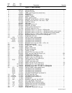
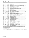
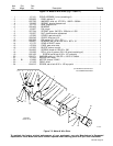
SECTION 7 – PARTS LIST
1
2
3
4
5
6 7
8
9
10
11
12
13
14
15
16
17
18
17
19 20
21
22
23
24
25
21
26
27
28
29
30
31
32
33
34
35
36
37
38
39
42
43
44
45
46
47
4849
50
51
52
53
54
55
56
5758
60
59
61
62
71
Fig 7-2
72
73
74
75 76 77 78 79
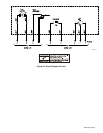
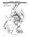
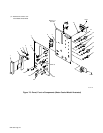
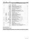
Figure 7-1. Main Assembly
Fig 7-3
63 64 65 66 67 70
68
69
4140
PC1
PC3
. Hardware is common and
not available unless listed.
143 223-D
. This main assembly drawing shows the XR-W
(water-cooled model). Some parts for the XR-A
(air-cooled model) vary in appearance. When
differences occur, they are called out in the part
description.