


6
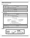
Mounting Specifications
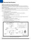
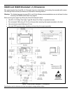
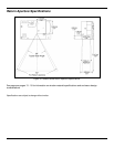
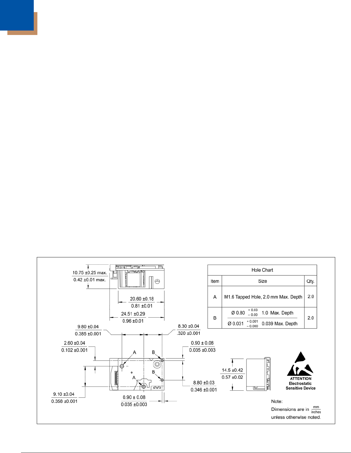
IS4813 and IS4815 Scan Engine Dimensions
The engine has two M1.6 tapped holes on the bottom of the chassis for mounting the engine with screws.
Two additional blind holes are provided on the bottom of the engine for keying purposes to assist with engine
alignment (see figure below).
Warning: The limited warranty (on page 38) is void if the following recommendations are not adhered to when
mounting the IS4800 series laser scan engine.
Follow the guidelines listed below when securing the engine to non-metallic or metallic mounting surfaces.
For a non-metallic mounting surface:
• Use non-magnetic M1.6 x .35 stainless steel screws.
• Do not exceed 1.35 ± .09 cm-kg [ 1.17 ± .08 in-lbs. ] of torque during screw installation.
• Use a minimum mount thickness of 3 mm.
• Use safe ESD practices when handling and mounting the engine.
For a metallic mounting surface:
• The die-cast engine chassis is at +Vcc. Use an insulator between the engine chassis and the host
(.005" thick PR4, or equivalent).
• Use non-metallic nylon or equivalent M1.6 x .35 screws.
• Do not exceeding 1.35 ± .09 cm-kg [ 1.17 ± .08 in-lbs. ] of torque.
• Use a minimum mount thickness of 3 mm.
• Use safe ESD practices when handling and mounting the engine.
Figure 6. IS4813 and IS4815 Engine Dimensions
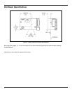
Specifications are for reference only and are subject to change without notice.