


28
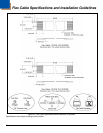
Scan Engine Terminations
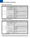
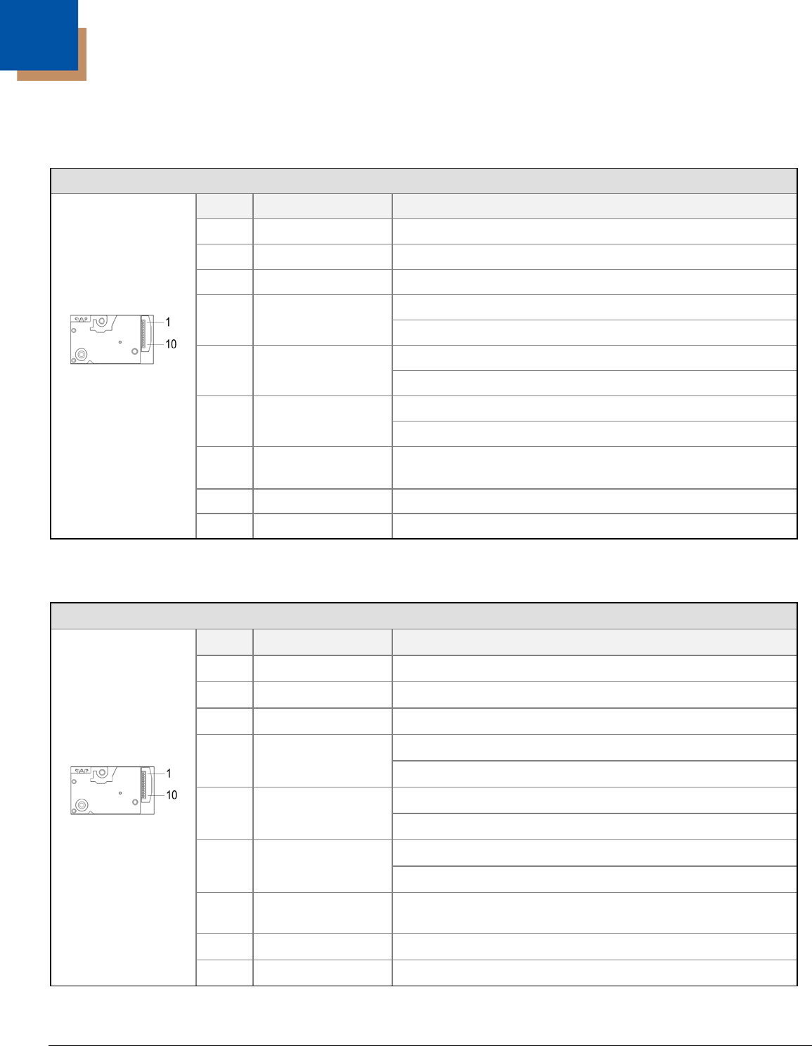
IS4813 Engine Connections
10-Pin ZIF Connector
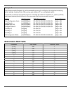
Figure 17. IS4813
Pin Signal Name Function
1 No Connect No Connect
2 Power, V 3.3V ± 0.3V
CC
3 No Connect No Connect
4 Laser Enable*
High = Laser OFF
Low = Laser ON, only if pin 5 (scan enable) is also Low
5 Scan Enable*
High = Engine OFF
Low = Engine ON
6
Digitized Bar
Pattern, Data Out
High = Bar
Low = Space
7
Start of Scan,
Scan Sense
Level changes from high to low, or low to high, when the
laser changes direction at the start of the scan line.
8 and 9
Ground Power Ground
10 No Connect No Connect
IS4815 Engine Connections
10-Pin ZIF Connector
Figure 18. IS4815
Pin Signal Name Function
1 No Connect No Connect
2 Power, V 5.0V ± 5%
CC
3 No Connect No Connect
4 Laser Enable*
High = Laser OFF
Low = Laser ON, only if pin 5 (scan enable) is also Low
5 Scan Enable*
High = Engine OFF
Low = Engine ON
6
Digitized Bar
Pattern, Data Out
High = Bar
Low = Space
7
Start of Scan,
Scan Sense
Level changes from high to low, or low to high, when the
laser changes direction at the start of the scan line.
8 and 9
Ground Power Ground
10 No Connect No Connect
* See Timing Diagrams on page 33.