


30
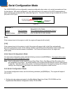
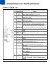
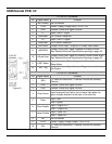
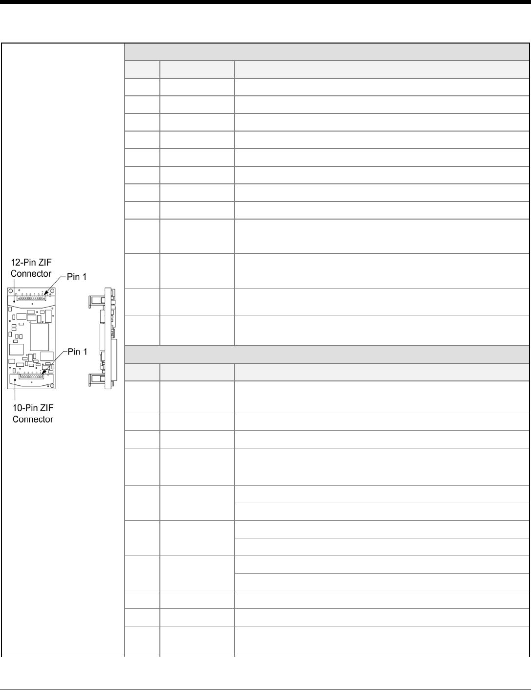
USB Decode PCB, 5V
Figure 20.
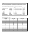
12-Pin ZIF Connector
Pin Signal Name Function
1 No Connect No Connection
2 +5.0V Power: Supply Voltage Input, +5.0V ± 5%
3 GND Ground: Power and Signal Ground
4 D- Input: USB D- Signal
5 <reserved> Pin Function Reserved
6 D+ Input: USB D+ Signal
7 <reserved> Pin Function Reserved
8 PWRDWN Output: Active High = Engine is in Power Down Mode
9 nBEEPER
Output: Active Low, Signal Capable of Sinking Current
See Detailed Electrical Specifications starting on page 26.
10 nGood Scan
Output: Active Low, Signal for Sinking Current (Good Scan)
See Detailed Electrical Specifications starting on page 26.
11 nEXT Wake
Input: Active Low, Wakes Engine from Power Down or
Sleep Mode
12 EXT Trig
Input: Active Low, Signal Used as Trigger Input to Activate
the Engine
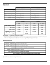
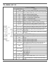
10-Pin ZIF Connector
Pin Signal Name Function
1 SDA
I
2
2
C Data (Bi-Directional) – Devices Function as Auxiliary
Devices
GND Ground: Power and Signal Ground
3 GND Ground: Power and Signal Ground
4 Scan Sense
Level changes from High to low or low to high when the
laser changes direction at the start of the scan line
5 Data
High = Bar
Low = Space
6 Scan Enable
High = Engine OFF
Low = Engine ON
7 Laser Enable
High = Laser OFF
Low = Laser ON
8 NC No Connection
9 +5.0V Power: Supply Voltage Output, +5.0V ± 5%
10 SCL
I
2
C Data (Bi-Directional) – Devices Function as Auxiliary
Devices