


11
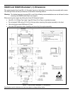
Enclosure Specifications
The IS4800 laser scan engine series was specifically designed for integration into custom housings for OEM
applications. The scan engine’s performance will be adversely affected or permanently damaged when
mounted in an unsuitable enclosure.
Note: THIS DEVICE DOES NOT COMPLY WITH 21 CFR 1040. USE ONLY AS COMPONENT.
The limited warranty (on page 38) is void if the following considerations are not adhered to when
integrating an IS4800 series scan engine into a system.
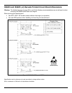
Electrostatic Discharge (ESD) Cautions
ESD has the ability to modify the electrical characteristics of a semiconductor device, possibly
degrading or even destroying the device. ESD also has the potential to upset the normal
operation of an electronic system, causing equipment malfunction or failure.
The scan engine has exposed electrical components.
• DO NOT touch the leads of the visible laser diode (VLD) or other components.
• ALWAYS use grounding wrist straps and a grounded work area when handling the engine.
• Mount the engine in a housing that is designed for ESD protection and stray electric fields.
Grounding
If the scan engine is to be installed in a grounded host:
• The die-cast engine chassis is at +Vcc. Use an insulator between the engine chassis and host.
• Use non-metallic nylon or equivalent screws.
Power Supply
The IS4813/IS4815 non-decode engines are powered from the host device through the 3.3V or 5V and GND
pins of the engine’s 10-Pin ZIF connector. IS4823/IS4825 decode engine assemblies are powered from the
host device through the 3.3V or 5V and GND pins of the 12-Pin ZIF connector on the decode board.
This voltage must be maintained within the specified voltage range (see electrical specifications on page 25)
at the engine’s PCB. Voltage drops in the host flex cable must be taken into account (see Flex Cables
on page 12).
Power Sequencing
The IS4813/IS4815 non-decode engines are powered from the 3.3V or 5V power signal on the 10-Pin ZIF
connector and the IS4823/IS4825 decode engine assemblies are powered from the 3.3V or 5V power signal on
the decode board. Most of the host signals (signals present on the ZIF connector) are relative to this voltage.
Not all of these signals are overvoltage tolerant. Care must be taken to ensure that the relationship between
3.3V or 5V and the host signals are always met (see electrical specifications on page
25).
See page 26 - 27 for additional electrical specifications.
See page 29 - 31 for additional pinout information.