


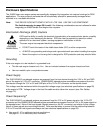
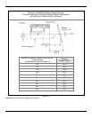
19
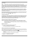
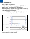
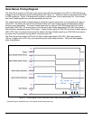
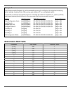
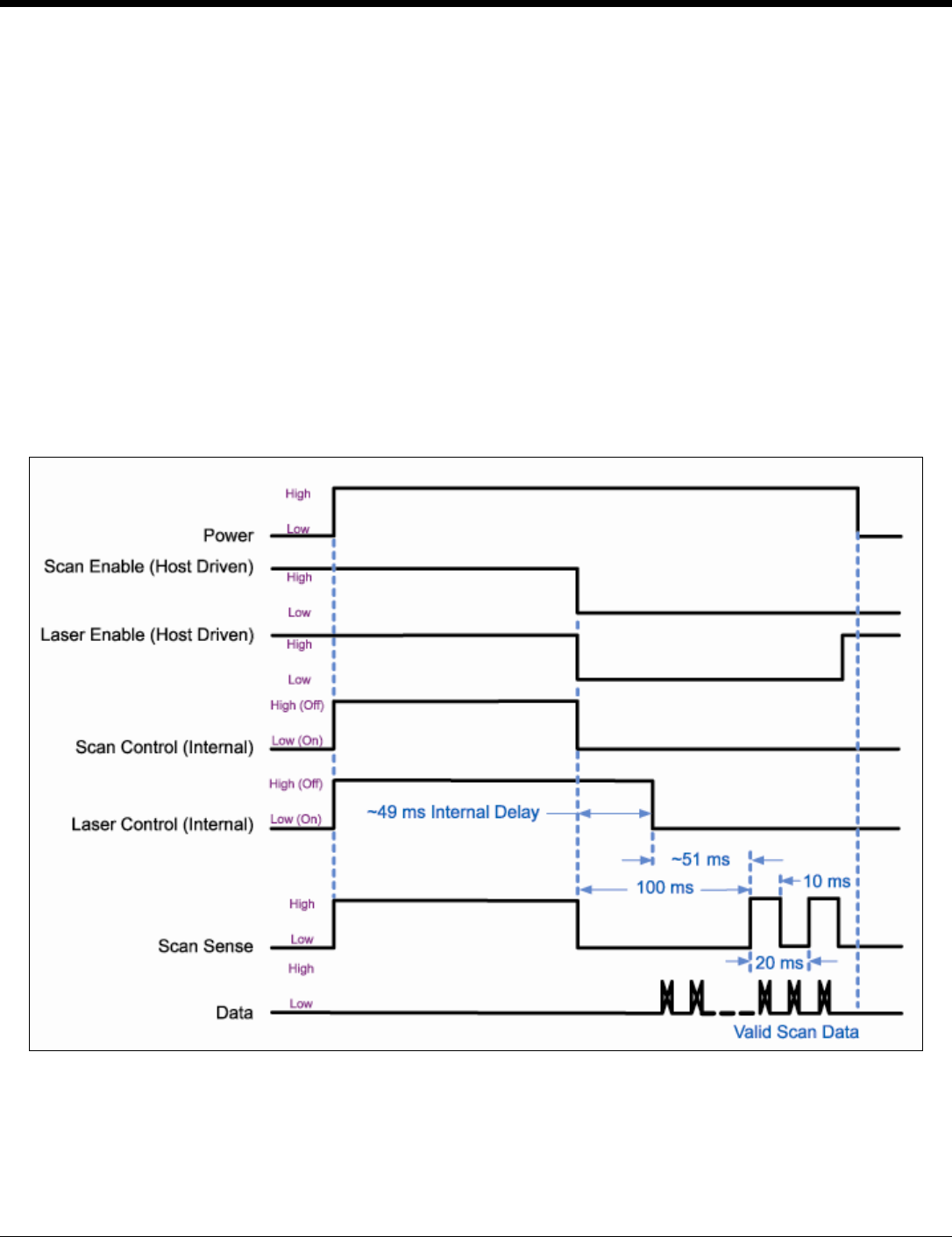
Scan Sense Timing Diagram
The Scan Sense signal is a 50% duty cycle square wave with the transitions from HIGH to LOW indicating a
change in the scan direction of the scanning beam (see Figure 14). Valid scan data occurs between the HIGH
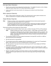
to LOW transitions. Figure 15 illustrates the condition in which power to the engine stays ON. Scan Enable
and Laser Enable signals are controlled separately by the host.
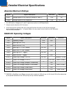
The onboard microcontroller is programmed to ensure the engine's scan mirror is moving before the laser is
turned ON. This allows the host to turn ON Scan Enable and Laser Enable signals simultaneously without
worrying about laser safety. The Laser Enable signal can even be set LOW (ON) before the Scan Enable
signal goes LOW (ON). If the scan mirror is moving and Laser Enable signal goes LOW (ON), the onboard
microcontroller immediately turns ON the laser. If Laser Enable signal is LOW (ON) and Scan Enable signal is
HIGH (OFF) then the onboard microcontroller waits for the Scan Enable signal to go LOW (ON) and ensures
the scan mirror has started moving before turning the laser ON.
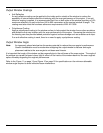
The Scan Sense line remains HIGH until the Scan Enable signal goes LOW (ON). After approximately
100 ms, it toggles with a 50% duty cycle representing the scan sweep direction. Valid scan data appears
within these pulses.
Figure 15. Timing Diagram Scan Enable and Laser Enable Controlled Separately*
* Typical timing for reference only, not to scale. Actual timing may vary.