


2 45481785_ed1
WARNING
Always wear eye protection when operating or performing maintenance on this tool.
Always turn o the air supply and disconnect the air supply hose before installing, removing or adjusting any accessory on this tool or
before performing any maintenance on this tool.
Note: When reading the instructions, refer to exploded diagrams in parts Information Manuals when applicable (see under Related
Documentation for form numbers).
Disassembly
General Instructions
1. Do not disassemble the tool any further than necessary to replace
or repair damaged parts.
2. Whenever grasping a tool or part in a vise, always use leather-
covered vise jaws to protect the surface of the part and help
prevent distortion. This is particularly true of threaded members
and housings.
NOTICE
Always use leather-covered vise jaws when clamping the handle
in a vise. Leather will conform to the shape of the handle and
allow the tool to be held securely. To prevent damage to the
exhaust diuser, never clamp only the bottom of the handle.
3. Do not remove any part which is a press t in or on a
subassembly unless the removal of that part is necessary for
repairs or replacement.
4. Do not disassemble the tool unless you have a complete set of
new gaskets and O-rings for replacement.
Disassembly of the Impact Wrench
1. Clamp the handle of the impact wrench in a vise with leather-
covered jaws with the square driver positioned horizontally.
NOTICE
Avoid excessive clamping pressure which can damage the
Housing and can cause diculty when removing the parts.
2. Unscrew and remove the four Hammer Case Screws (11).
3. While lightly tapping on the end of the Anvil (8) with a plastic
hammer, lift o the Hammer Case (15) and Hammer Case Gasket (18).
NOTICE
The Front End Plate (2) might come o during the removal of the
Hammer Case. Make sure that it does not drop on the oor or
strike a hard or metallic surface since it might be damaged.
4. Grasp the Hammer Frame (12) and carefully lift o the entire impact
mechanism, making certain not to drop the two Hammer Pins (13).
Disassembly of the Impact Mechanism
1. Set the mechanism, driver end up, on the workbench.
NOTICE
Note the twin hammers within the Hammer Frame. These are
identical, but must be placed in the Hammer Frame in a certain
relationship. Using a felt-tipped pen, mark he top “T” hammer
and the bottom hammer “B” with the arrows pointing upward.
Mark both Hammers on the same end.
2. With the mechanism sitting upright on the workbench, slowly
rotate the Anvil in a clockwise direction until it comes up solid.
NOTICE
If you continue to rotate the Anvil, it will cam the Hammers out
of engagement. Don’t do this; merely rotate the Anvil until it
comes up solid.
3. Hold the Hammer Frame rmly and without disturbing the
hammers, gently lift the Anvil while simultaneously rotating it
clockwise about 1/8 of a turn, from the Hammer Frame.
4. With the Anvil removed, lift out the two Hammer Pins.
NOTICE
The twin hammers are now free to slide from the Hammer Frame.
Be careful not to drop them.
Disassembly of the Motor
NOTICE
When pulling, disassembling or assembling the motor, we
recommend replacement of the Motor Gasket (7).
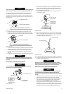
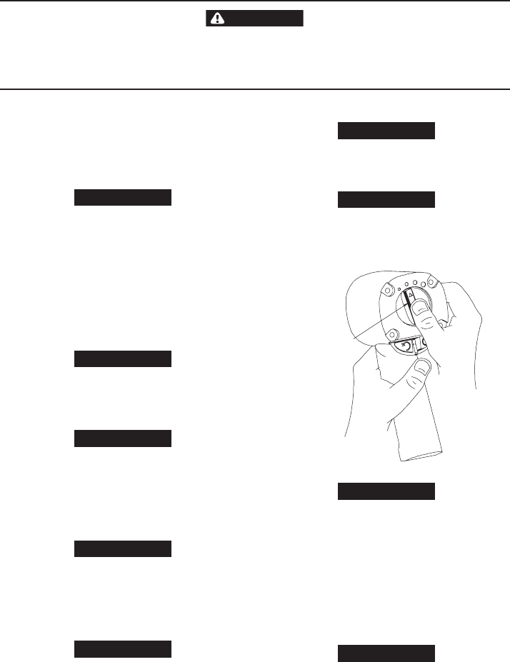
1. Remove the Motor Assembly from the Housing (19) by pushing
on Power Management Dial (35) from the back of the Housing.
Refer to Dwg. TPD1322.
POWER
MANAGEMENT
DIAL
(Dwg. TPD1322)
NOTICE
If the Motor Assembly cannot be removed from the Housing by
pushing, tap the Power Management Dial lightly until the Motor
Assembly is free.
2. Remove the Silencer (6A) from the top of the Cylinder (1). Remove
the Power Management Dial from the rear of the Cylinder (1).
Remove the Power Management Dial Seal (5A) if it needs to be
replaced.
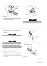
3. Remove the Front End Plate (2) from the Cylinder by tapping the
splined end of the Rotor (5) with a plastic hammer. If the Front
End Plate does not come loose, secure a center punch in a vise
with the point angled downward and outward from the vise.
Grasp the Cylinder and Front End Plate in one hand and position
the hole in the end of the Rotor against the punch.
NOTICE
Be careful not to drop the Cylinder since it can be damaged by
hitting a hard surface.
Using the other hand, tap the punch with a hammer while pressing
the Rotor against the punch. After a few taps, the Front End Plate will
slide o of the Cylinder.