


45481785_ed1 3
NOTICE
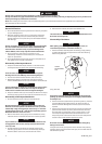
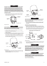
To prevent damage to the Cylinder, do not tap or strike Cylinder on
a hard or metallic surface when removing the Rotor Bearings (3).
To remove the Front Rotor Bearing, hold the Front End Plate with
Front Rotor Bearing down and tap the Front End Plate on a at,
nonmetallic surface such as a work bench. This will loosen the Front
Rotor Bearing so that it will drop out of the Front End Plate. Refer to
Dwg. TPD1323.
FRONT END PLATE
FRONT ROTOR BEARING
BENCH WITH NONMETALLIC SURFACE
(Dwg. TPD1323)
4. Remove the Rear Rotor Bearing Retainer (6) from the rear of
the Rotor (5). The Rotor can now be removed from the Cylinder.
Remove the Vanes (4) from the Rotor if they need to be replaced.
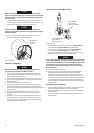
CYLINDER
REAR ROTOR BEARING
BENCH WITH NONMETALLIC SURFACE
(Dwg. TPD1324)
5. To remove the Rear Rotor Bearing, hold the Cylinder with the Rear
Rotor Bearing down and tap the Cylinder on a at, nonmetallic
surface such as a work bench. This will loosen the Rear Rotor
Bearing so that it will drop out of the Cylinder. Refer to Dwg.
TPD1324.
6. Working from the rear of the Housing, push out the Motor Gasket (7).
NOTICE
When removing the Motor Gasket, do not use a screwdriver or
any other sharp object which could damage the Gasket and/or
Housing.
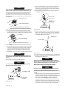
Disassembly of the Throttle Mechanism
NOTICE
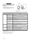
For ease of disassembly, we recommend using the Inlet Clip
Removal Tool (36). See Dwg. TPD1681.
LEFT-HAND BUTTON
INLET BUSHING
INLET CLIP
REMOVAL TOOL
ASSEMBLY
TRIGGER
(Dwg. TPD1681)
1. Secure the Inlet Bushing in a vise. Press in both tabs of the Inlet
Retainer Clip (27) and pull upward on the Housing (19). This
will allow the Inlet Bushing to come free from the Handle of the
Housing. Refer to Dwg. TPD1326.
2. Pull the Trigger (28) from the front of the Housing and remove
the Trigger O-ring (2A).
SLOT FOR TAB
(BOTH SIDES)
TAB ON INLET
RETAINER CLIP
(BOTH SIDES)
(Dwg. TPD1326)
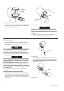
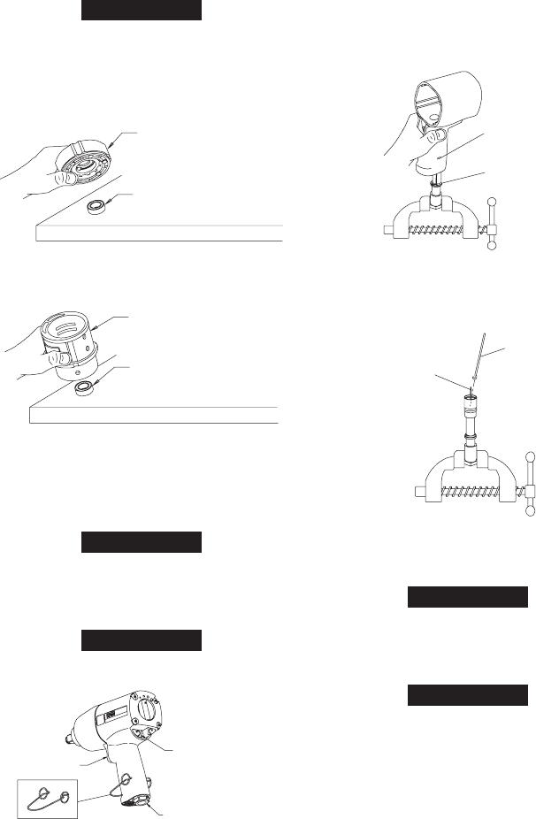
3. With the Inlet Bushing still in the vise, remove the Tilt Valve Seat
Retainer (1G) and Tilt Valve Seat Support (1F). Use a hooked tool
with no sharp edges to remove the Tilt Valve Seat (1E) from the
Inlet Bushing. Refer to Dwg. TPD1327.
TILT VALVE STEM
HOOKED TOOL
(Dwg. TPD1327)
4. Remove the Tilt Valve (1D) and Tilt Valve Spring (1C) if damaged.
5. Remove the Inlet Bushing Seal (1B) and Inlet Retainer Clip (27) if
damaged. Remove Washer (1A).
NOTICE
Do not remove the Inlet Bushing Screen (20A) from the Inlet
Bushing unless it is damaged. Clean the Inlet Bushing Screen by
using a suitable cleaning solution in a well ventilated area.
Disassembly of the Reverse Valve Mechanism
NOTICE
The Reverse Valve Assembly cannot be removed without rst
removing the Forward and Reverse Buttons (4A) and (4B).
Therefore, it is important that the procedure below be followed
exactly.
1. Notice the notches on either side of the partition. These notches
indicate the correct location for insertion of a thin-bladed
screwdriver used for removing the Forward and Reverse Buttons.
Insert the screwdriver between the partition and the Button
which is fully extended. Gently pry against the Button to
disengage the detent so that the Button can be removed. After
the Button is removed, reach inside the Housing and rotate the
Reverse Valve to extend the remaining Button. Repeat the above
procedure for the remaining Button. Refer to Dwg. TPD1328.