


4 45481785_ed1
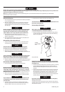
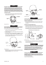
REMOVAL OF
FORWARD/
REVERSE
BUTTONS
(Dwg. TPD1328)
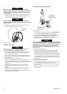
2. Insert thumb into the front of the Housing and push down on the
Reverse Valve so that it can be removed through the bottom of
the handle. Refer to Dwg. TPD1329.
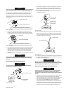
REVERSE
VALVE
(Dwg. TPD1329)
NOTICE
Do not try to remove the Reverse Valve by pushing upward. It
can only be removed by pushing it downward and out of the
bottom of the handle. If the Reverse Valve does not come free,
tap the bottom of the handle lightly with a rubber hammer until
it drops out.
3. Remove the Top Reverse Valve O-ring (3A) and the Bottom
Reverse Valve O-ring (3B) from the Reverse Valve.
Assembly
General Instructions
1. Whenever grasping a tool or part in a vise, always use leather-
covered vise jaws to protect the surface of the part and help
prevent distortion. This is particularly true of threaded members
and housings.
NOTICE
Always use leather-covered vise jaws when clamping the handle
in a vise. Leather will conform to the shape of the handle and
allow the tool to be held securely. To prevent damage to the
exhaust diuser, never clamp only the bottom of the handle.
2. Always clean every part and wipe every part with a thin lm of oil
before installation.
NOTICE
Do not remove grease from the impact mechanism or Hammer
Case (15). If the impact mechanism has not been disassembled,
inject Ingersoll Rand No. 115-1LB Grease through the Hammer
Case Grease Fitting (17).
When disassembling and assembling the impact mechanism,
remove all grease from the impact mechanism and Hammer Case
and lubricate the impact mechanism and Hammer Case Bushing
(16) with Ingersoll Rand No. 105-1LB Grease or Ingersoll Rand
No. 105-8LB Grease.
3. Apply a lm of o-ring lubricant to all O-rings before nal
assembly.
Assembly of the Reverse Valve Mechanism
1. Install the Bottom Reverse Valve O-ring (3B) (color-coded blue)
and the Top Reverse Valve bring (3A) on the Reverse Valve (30).
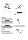
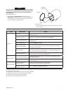
2. Insert the Reverse Valve in the bottom of the handle making sure
that two ears on the Reverse Valve are facing downward. Refer to
Dwg. TPD1330.
EARS
(Dwg. TPD1330)
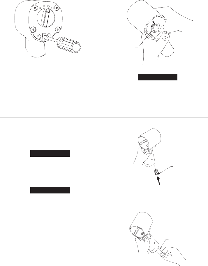
Use a wooden dowel to push the Reverse Valve up through
the handle until the top of the Reverse Valve is ush with or
slightly above the bottom of the motor bore in the Housing
(19). Refer to Dwg. TPD1331.
DOWEL
(Dwg. TPD1331)