


45481785_ed1 5
NOTICE
If the Reverse Valve is pushed up too far and becomes wedged,
it will have to be pushed back down through the handle and
re-inserted from the bottom of the handle. The Reverse Valve
cannot be removed by pushing it up through the handle and
into the motor bore. If the Reverse Valve must be removed and
re-installed, make sure that the Top and Bottom Reverse Valve
O-rings have not been rolled o and are in their proper positions
on the Reverse Valve.
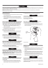
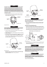
3. When the Reverse Valve has been installed, rotate the Reverse
Valve so that the tab on the Reverse Valve is at the rear of the
Housing. Refer to Dwg. TPD1332.
FRONT OF
HOUSING
APPROX. 1/32”
REVERSE
VALVE
(Dwg. TPD1332)
NOTICE
If the orientation of the Reverse Valve is not correct (tab facing
the rear of the Housing), the Trigger (28) and the Forward and
Reverse Buttons (4A) and (4B) cannot be installed.
4. Install the Trigger O-ring (2A) on the Trigger. Insert the Trigger
Assembly in the front of the Housing.
5. Rotate the Reverse Valve in either direction until an ear comes up
against the Trigger.
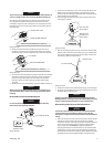
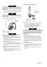
6. Look through the Housing from the rear. If the tab on the Reverse
Valve has been rotated to the left, install the right Button in the
Housing. When one Button has been installed, push the Button
in. This will rotate the’ Reverse Valve so that the other Button can
be installed. Refer to Dwg. TPD1333.
REVERSE
VALVE
FORWARD
BUTTON
REAR OF
HOUSING
TAB
(Dwg. TPD1333)
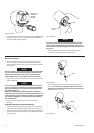
If the tab on the reverse Valve has been rotated to the right,
install the left Button. Refer to Dwg. TPD1334.
REVERSE
VALVE
REVERSE
BUTTON
TAB
REAR OF
HOUSING
(Dwg. TPD1334)
NOTICE
If the Forward/Reverse Buttons will not install easily, move the
Reverse Valve slightly higher in the handle to provide better
alignment with the Buttons.
7. After the Forward/Reverse Buttons have been installed, remove
the Trigger before proceeding with installation of the throttle
mechanism.
Assembly of Throttle Mechanism
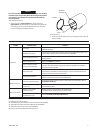
1. Using an Inlet Bushing Screen Installation Tool, install the Inlet
Bushing Screen (20A), screened end rst, in the bottom (hex end)
of the Inlet Bushing (20). Insert the rounded end of the tool in the
cone formed by the screen and tap the end of the tool to secure
the rim of the screen in the Bushing. Refer to Dwg. TPD1473.
Inlet Bushing Screen Installation Tool
0
(Dwg. TPD1473)
2. Install the Washer (1A), Inlet Retainer Clip (27), Inlet Bushing Seal
(1B), Tilt Valve Spring (1C), Tilt Valve (1D) Tilt Valve Seat (1E) and
Tilt Valve Seat Support (1F).
WARNING
The Tilt Valve Seat Retainer (1G) must be properly installed in the
groove in the Inlet Bushing (20). To check for correct installation
of the Retainer, insert a pin into one of the holes in the Retainer
and rotate the Retainer. A correctly installed Retainer will
rotate freely but with some resistance in the groove of the Inlet
Bushing. An incorrectly installed Retainer will pop out of the
Inlet Bushing when the Retainer is rotated.
WARNING
Do not use compressed air to check installation of the Tilt Valve
Seat Retainer or Inlet Bushing Screen unless the entire Inlet
Bushing Assembly is installed in the tool with the Hammer Case
installed and properly secured to the Motor Housing. Failure to
do so could result in injury.
Install the Tilt Valve Seat Retainer.