


6 45481785_ed1
NOTICE
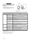
When re-installing the Inlet Bushing Assembly (20), pull the
Trigger (28) outward and make sure that the Reverse Button (4B)
is depressed before snapping the Inlet Bushing Assembly back
into the Housing.
3. Install the Inlet Bushing Assembly by pushing it into the hole in
the Housing until you see and hear the tabs on Inlet Retainer Clip
snap into place through the slots in Housing handle.
NOTICE
The Reverse Button (left) (4B) must be pushed in before the
Trigger can be installed. Otherwise, the Trigger will be damaged
during installation.
4. Install the Trigger by pushing it into the handle until a click is
heard indicating that it is properly engaged.
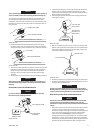
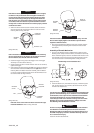
INSTALLATION
OF MOTOR
GASKET
(Dwg. TPD1336)
Assembly of the Motor
NOTICE
When disassembling, assembling or pulling the Motor, we
recommend replacement of the Motor Gasket (7).
1. Install the Motor Gasket in the Housing making sure that the
grooves in the tab of the Motor Gasket t around ridge in the
Housing. Refer to Dwg. TPD1336.
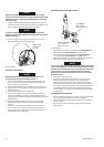
2. Install the Rear Rotor Bearing (3) into the rear of the Cylinder (1).
3. Install the Rotor in the Cylinder and secure with the Rear Rotor
Bearing Retainer (6).
4. Install Vanes (4) in the slots in the Rotor (5).
5. Install the Front Rotor Bearing (3) into the Front End Plate (2).
Install the Front End Plate on the Cylinder by pressing on the
inner race of the front Rotor Bearing until the Bearing is seated on
the Rotor Shaft.
6. Install the Power Management Dial Seal (5A) on the Power
Management Dial (35) and install the Dial in the end of the
Cylinder.
7. Clean the Silencer (6A) using a suitable cleaning solution in a
well-ventilated area. Position the Silencer over the top of the
Cylinder and insert the Motor Assembly into the Housing (19),
Power Management Dial end rst.
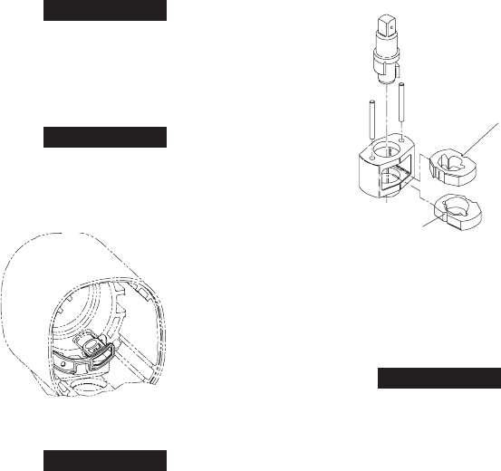
Assembly of the Impact Mechanism
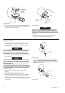
TOP HAMMER
HALF--ROUND
NOTCH O N RIGHT
BOTTOM HAMMER
HALF--ROUND
NOTCH O N LEFT
(Dwg. TPD1535)
1. Coat the Hammers (14) with a light lm of No. Ingersoll Rand
105-1LB Grease or Ingersoll Rand No. 105-8LB Grease.
2. Heavily coat the jaws of the Anvil (8) with Ingersoll Rand No.
105-1LB Grease or Ingersoll Rand No. 105-8LB Grease.
3. Replace the Hammers in the Hammer Frame (12) exactly as they
were when you marked them prior to disassembly.
NOTICE
If you are installing new Hammers or want to change the location
of the existing Hammers to utilize both impacting surfaces, slide
the Hammers in the Hammer Frame so that the half-round notch
on one Hammer is located on one side of the Frame and the
half-round notch on the other Hammer is located on the other
side of the Frame.
4. Replace the Hammer Pins (13).
5. Examine the base of the Anvil (8) and note its contour. While
looking down through the Hammer Frame, swing the top
Hammer to its full extreme one way or another until you can
match the contour of the Anvil. Enter the Anvil into the Hammer
Frame and through the rst Hammer. Swing the bottom Hammer
in the opposite direction from the top Hammer and maneuver
the Anvil slightly until it drops into the bottom Hammer. Refer to
Dwg. TPD1535.
Assembly of the Air Wrench
1. Position the Motor Housing (19) in leather-covered vise jaws with
the splined shaft of the Rotor in a horizontal position.
2. Place the assembled impact mechanism down onto the splined
hub of the Rotor.
3. Position the Hammer Case Gasket (18) against the face of the
Motor Housing.