


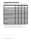
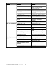

36
7/120 (P425AWIR), 9/110 (XP375AWIR), 10/105 (HP375AWIR), 14/85 (VHP300AWIR),
7/170 (P600WIR), 10/125 (HP450WIR), 14/115 (VHP400WIR)
At Fuel Injection Nozzles
IMPORTANT: Always use a backup wrench
when loosening or tightening fuel lines at
nozzles and/or injection pump to avoid
damage.
1. Using two open–end wrenches, loosen two
fuel line connections at injection nozzles.
2. Crank engine over with starter motor for 15
seconds (but do not start engine) until fuel
free from bubbles flows out of loosened
connection. Retighten connection to
specifications.
Specification
Fuel Injection Nozzle Delivery
Lines—Torque 27 N•m (20 lb–ft)
3. Repeat procedure for remaining injection
nozzles (if necessary) until all air has been
removed from fuel system.
If engine still will not start, see your authorized
servicing dealer or engine distributor.
Do Not Modify Fuel System
IMPORTANT: Modification or alteration of
the injection pump, the injection pump
timing, or the fuel injectors in ways not
recommended by the manufacturer will
terminate the warranty obligation to the
purchaser.
In addition, tampering with fuel system
which alters emission–related equipment on
engines may result in fines or other
penalties, per EPA regulations or other local
emission laws.
Do not attempt to service injection pump or
fuel injectors yourself. Special training and
special tools are required. (See your
authorized servicing dealer).
Troubleshooting
General Troubleshooting Information
Troubleshooting engine problems can be
difficult.
In this section is a list of possible engine
problems that may be encountered
accompanied by possible causes and
corrections. The illustrated diagrams and
troubleshooting information are of a general
nature. See your engine distributor or servicing
dealer if you are in doubt.
A reliable program for troubleshooting engine
problems should include the following basic
diagnostic thought process:
S Know the engine and all related systems.
S Study the problem thoroughly.
S Relate the symptoms to your knowledge of
engine and systems.
S Diagnose the problem starting with the
easiest things first.
S Double–check before beginning the
disassembly.
S Determine cause and make a thorough
repair.
S After making repairs, operate the engine
under normal conditions to verify that the
problem and cause was corrected.
NOTE: The engines covered in this manual
have electronic control systems which send
diagnostic trouble codes to signal problems.
Precautions For Welding On Engines
Equipped With Electronic Engine Control
Unit (ECU)
IMPORTANT: ALWAYS disconnect Electronic
Control Unit (ECU) connectors and engine
control system–to–machine ground before
welding on engine or machine. High
currents or electro–static discharge in
electronic components from welding may
cause permanent damage.
1. Remove the ground connection for the
engine control system–to–machine frame.
2. Disconnect the connectors from the ECU.
3. Connect the welder ground close to the
welding point and be sure ECU or other
electronic components are not in the ground
path.