


51
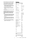
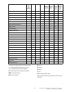
7/120 (P425AWIR), 9/110 (XP375AWIR), 10/105 (HP375AWIR), 14/85 (VHP300AWIR),
7/170 (P600WIR), 10/125 (HP450WIR), 14/115 (VHP400WIR)
FUEL FILTER WATER SEPARATOR
The fuel filter water separator contains a filter element which
should be replaced at regular intervals (see the
SERVICE/MAINTENANCE CHART).
CHARGE AIR COOLER PIPEWORK
Inspect all hoses and clips on the charge cooler pipe work.
Engine damage will occur if the charge cooling system leaks.
HOSES
All components of the engine cooling air intake system
should be checked periodically to keep the engine at peak
efficiency.
At the recommended intervals, (see the
SERVICE/MAINTENANCE CHART), inspect all of the intake
lines to the air filter, and all flexible hoses used for air lines, oil
lines and fuel lines.
Periodically inspect all pipework for cracks, leaks, etc. and
replace immediately if damaged.
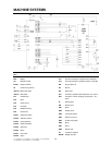
ELECTRICAL SYSTEM
WARNING: Always disconnect the battery cables before
performing any maintenance or service.
Inspect the safety shutdown system switches and the
instrument panel relay contacts for evidence of arcing and
pitting. Clean where necessary.
Check the mechanical action of the components.
Check the security of electrical terminals on the switches
and relays i.e. nuts or screws loose, which may cause local hot
spot oxidation.
Inspect the components and wiring for signs of overheating
i.e. discolouration, charring of cables, deformation of parts,
acrid smells and blistered paint.
BATTERY
Keep the battery terminals and cable clamps clean and
lightly coated with petroleum jelly to prevent corrosion.
The retaining clamp should be kept tight enough to prevent
the battery from moving.
PRESSURE SYSTEM
At 500 hour intervals it is necessary to inspect the external
surfaces of the system (from the airend through to the discharge
valve(s)) including hoses, tubes, tube fittings and the separator
tank, for visible signs of impact damage, excessive corrosion,
abrasion, tightness and chafing. Any suspect parts should be
replaced before the machine is put back into service.
TYRES/TYRE/TIRE PRESSURE
See the GENERAL INFORMATION section of this manual.
RUNNING GEAR/WHEELS
Check the wheel nut torque 20 miles (30 kilometres) after
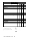
refitting the wheels. Refer to the TORQUE SETTING TABLE
later in this section.
Lifting jacks should only be used under the axle.
The bolts securing the running gear to the chassis should be
checked periodically for tightness (refer to the
SERVICE/MAINTENANCE CHART for frequency) and
re–tightened where necessary. Refer to the TORQUE
SETTING TABLE later in this section.
BRAKES
Check and adjust the brake linkage at 500 miles (850Km)
then every 3000 miles (5000Km) or 3 months (whichever is the
sooner) to compensate for any stretch of the adjustable cables.
Check and adjust the wheel brakes to compensate for wear.
CAUTION: Check the wheel nut torque 20 miles (30 kilometres)
after refitting the wheels (Refer to the TORQUE SETTING
TABLE later in this section).
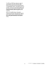
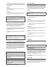
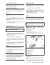
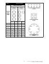
Adjusting the overrun braking system
(KNOTT Running Gear)
1: Preparation
Jack up the machine
Disengage the handbrake lever [1].
Fully extend the draw bar [2] on the overrun braking system.
1 Handbrake lever
2 Draw bar and bellows
3 Handbrake lever pivot
4 Transmission lever
5 Brake cable
6 Breakaway Cable
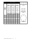
Requirements:
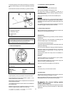
During the adjustment procedure always start with the wheel
brakes.
Always rotate the wheel in the direction of forward movement.
Ensure that an M10 safety screw is fitted to the handbrake pivot.